Download
1 / 28
320 likes | 794 Views
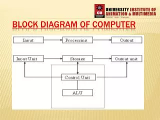
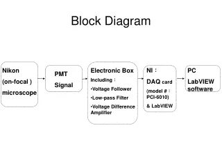
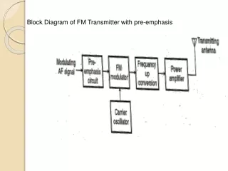
Block Diagram of FM Transmitter with pre-emphasis. Relationship between FM and PM. ( a ) FM scheme by using a phase modulator. ( b ) PM scheme by using a frequency modulator. FM Capture effect

E N D
Relationship between FM and PM. (a) FM scheme by using a phase modulator. (b) PM scheme by using a frequency modulator.
FM Capture effect In telecommunication, the capture effect, or FM capture effect, is a phenomenon, associated with FM reception, in which only the stronger of two signals at or near the same frequency will be demodulated. The capture effect is defined as the complete suppression of the weaker signal occurs at the receiver limiter, if it has one, where it is not amplified, but attenuated. When both signals are nearly equal in strength, or are fading independently, the receiver may switch from one to the other.
PULSE MODULATION In pulse modulation method the carrier is no longer a continuous signal but consists of pulse train, some parameter varied according to the modulating signal.
Starts with Sampling Volts time
Sampling process Analog signal Pulse amplitude modulated (PAM) signal SAMPLING THEOREM • Sampling theorem: A bandlimited signal with no spectral components beyond fm , can be uniquely determined by values sampled at uniform intervals of • The sampling rate, • is called Nyquist rate.
Sampling Time domain Frequency domain
PULSE MODULATION The process of transmitting signals in the form of pulses (discontinuous signals) by using special techniques. • Pulse Amplitude Modulation • Pulse Width Modulation • Pulse Position Modulation • Pulse Code Modulation
Pulse Code (PCM) Pulse Amplitude (PAM) Pulse Width (PWM) Delta (DM) Pulse Position (PPM) Pulse Modulation Analog Pulse Modulation Digital Pulse Modulation
Pulse Amplitude Modulation (PAM): • The signal is sampled at regular intervals such that each sample is proportional to the amplitude of the signal at that sampling instant • Types of PAM: 1. Natural PAM 2. Flat top PAM Analog Signal Amplitude Modulated Pulses
2. Flat top PAM Transmission Bandwidth
Advantages :- • Simplicity of generation and detection. • Disadvantages :- • Since the amplitude of carrier pulses carries the information , the interference of noise is maximum. • BW is too large than max. freq fm. • The peak power required by transmitter varies with modulating signal.
Pulse Width Modulation (PWM or PLM or PDM): * In this type, the amplitude is maintained constant but the duration or length or width of each pulse is varied in accordance with instantaneous value of the analog signal. Analog Signal Width Modulated Pulses
Pulse Width Modulation: time min = largest Negative max = largest Positive
Advantages :- • PWM is more immune to noise since information is carried by width of pulse. • Synchronization is not required as in PPM between Tx and Rx. • Disadvantages :- • BW is larger than PAM. • In PWM the pulses are varying in width so the peak power at output is variable
Pulse Position Modulation (PPM): • In this type, the sampled waveform has fixed amplitude and width whereas the position of each pulse is varied as per instantaneous value of the analog signal. PPM
PAM, PWM and PPM at a glance: Analog Signal Amplitude Modulated Pulses Width Modulated Pulses Position Modulated Pulses