Future Challenges in e+e- Linear Collider Energy and Luminosity
R. Brinkmann from DESY outlines critical challenges facing future e+e- linear colliders at the 2003 EPS-HEP Conference in Aachen. The presentation emphasizes the energy and luminosity requirements necessary for advancing linear collider technology, highlighting the significant increases needed (e.g., from 0.5 to 1 TeV and over 10^34 cm^-2 s^-1). Brinkmann discusses innovative techniques developed through previous projects like the SLC, emphasizing the necessity for sophisticated modeling, trajectory corrections, and advanced beam diagnostics to achieve the desired performance and stability.

Future Challenges in e+e- Linear Collider Energy and Luminosity
E N D
Presentation Transcript
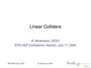
Linear Colliders R. Brinkmann, DESY EPS-HEP Conference, Aachen, July 17, 2003 R. Brinkmann, DESY
The energy and luminosity challenges for a future e+e- linear collider: “It’s only an order of magnitude in energy (0.5 1 TeV) and three to four orders of magnitude in luminosity (>1034 cm-2 s-1) from the SLC…” R. Brinkmann, DESY
Lessons from the SLC • New Territory in Accelerator Design and Operation • Sophisticated on-line modeling of non-linear beam physics. • Correction techniques (trajectory and emittance), from hands-on by operators to fully automated control, slow/fast feedback theory and practice. R. Brinkmann, DESY
FFTB beamline at the end of the SLAC linac. FFTB Collaboration BINP (Novosibirsk/Protvino) DESY Fermilab IBM Kawasaki KEK LAL (Orsay) MPI(Munich) Rochester SLAC 1997 1994 Vertical beam size of 60-70 nm … demagnification needed for any LC. R. Brinkmann, DESY
Linear Collider Parameter Overview R. Brinkmann, DESY
International Linear Collider Technical Review Committee 2nd Report 2003 (480 pages), Chair: G. Loew, SLAC www.slac.stanford.edu/xorg/ilc-trc/2002/2002/report/03rep.htm • Asses technical status of 500 GeV LC designs • Potential for reaching higher energies • Identify R&D work to be done ranking list R1(feasibility demonstration) … R4(desirable for technical/cost optimisation) R. Brinkmann, DESY
500( 800)GeV e+e- Linear Collider Based on superconducting linac technology R. Brinkmann, DESY
Why superconducting? • High efficiency ACbeam (>20%, ~10% normal c.) • Low frequency: • Long pulses with low RF peak power • Small beam perturbations from wakefields • Intra-train feedback on beam orbit, energy, luminosity… • First proposed in 1960s (M. Tigner)… show stopper was too low acc. Gradient, too high cost R. Brinkmann, DESY
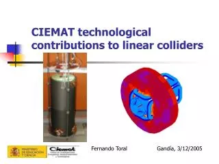
Accelerating gradient on test stand reached 25 MV/m on average for 1999/2000 cavity production R. Brinkmann, DESY
Test of complete accelerator modules in the TTF linac at DESY (>13,000h beam operation 1997 - 2003) R. Brinkmann, DESY
Higher performance cavities: energy reach 800 GeV 1st step: no add. investment, 2nd step: add cryo+RF power R. Brinkmann, DESY
Improvement of Nb surface quality with electro-polishing (pioneering work done at KEK) BCP EP • Several single cell cavities at g > 40 MV/m • 4 nine-cell cavities at ~35 MV/m R. Brinkmann, DESY
CHECHIA test in pulsed mode TESLA 500 – 800 design R. Brinkmann, DESY
X-band technology(SLAC/KEK & coll. Inst.) NLC SLC-like 20MV/m, 3 GHz 50MV/m (65 unloaded), 11.4GHz R. Brinkmann, DESY
The NLCTA with 1.8 m accelerator structures (ca 1997). Demonstration of X-band concept, wakefield control, beamloading compensation,… But:acc. Gradient limited < 40 MV/m R. Brinkmann, DESY
Structure damage from RF breakdown R. Brinkmann, DESY
Snowmass 2001 R. Brinkmann, DESY
Test Structure Run History (T-Series 2003, not final version for linac) 1 Trip per 25 Hrs Unloaded Gradient (MV/m) NLC/JLC Goal: Less than 1 trip per 10 Hrs at 65 MV/m 400 ns Pulse Width No Observed Change in Microwave Properties Time with RF On (hr) R. Brinkmann, DESY
CLIC two-beam accelerator approachCERN & coll. Inst. R. Brinkmann, DESY
Successful demonstration of 30 GHz two-beam concept at CTF-II But: serious structure damage from RF breakdown at high gradient R. Brinkmann, DESY
Systematic study of high-g RF breakdown/damage problem: RF breakdown vs. frequency damage vs. different material of irises (Cu, W, Mo) R. Brinkmann, DESY
LOW CURRENT BUNCH TRAIN COMBINATION streak camera images of beam in the ring 1st turn - 1st bunch train from linac time 2nd turn • First demonstration in June 2002 • Tested combination factors 4 & 5 3rd turn Final intensity profile 4th turn combination factor 4 CTF3 (under construction) R. Brinkmann, DESY
Luminosity challenge:beam quality & stability • Damping rings: emittances required ~factor 3…5 below best values obtained to date at SR sources and ATF-DR (KEK) • Wakefields fRF3 tighter alignment tolerances & more precise beam diagnostics for higher frequency linacs • Dynamic stability: higher rep. Rate of n.c. linacs compensates (partially) for tighter tolerances R. Brinkmann, DESY
Luminosity stability: “Start-to-end” simulations, including ground motion 50 s 2 s R. Brinkmann, DESY
Power spectral density Ground motion: varies form “quiet” (model A) to “noisy” (model C), depending on site R. Brinkmann, DESY
Seismic measurements: TESLA LC central site (Ellerhoop) more quiet than HERA (data taken on a Monday, 0.00h – 1.00h) HERA tunnel Ellerhoop (barn) R. Brinkmann, DESY
There are a number of subtle effects in LC beam dynamics… e.g. the banana effect (amplification of bunch deformations during collision): (TESLA beam-beam simulation) R. Brinkmann, DESY
Choice of technology: hybrid collider?? superconducting Normal conducting Doesn’t work…. R. Brinkmann, DESY
Towards a Global Linear Collider… • International Linear Collider Steering Committee (Chair: M. Tigner, Cornell) will select the linac technology with the help of a group of “Wise persons” (~ mid 2004) • Establish GLC design group Technical Design Report as basis for site selection and project approval • Worldwide organisation at political level • Start project construction ~2007 R. Brinkmann, DESY