Download
1 / 17
180 likes | 382 Views
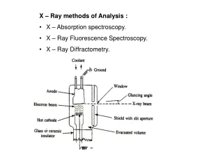
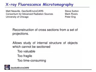
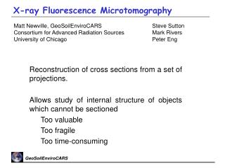
Matt Newville, GeoSoilEnviroCARS Consortium for Advanced Radiation Sources University of Chicago. Steve Sutton Mark Rivers Peter Eng. X-ray Fluorescence Microtomography. Reconstruction of cross sections from a set of projections.

E N D
Matt Newville, GeoSoilEnviroCARS Consortium for Advanced Radiation Sources University of Chicago Steve Sutton Mark Rivers Peter Eng X-ray Fluorescence Microtomography • Reconstruction of cross sections from a set of projections. • Allows study of internal structure of objects which cannot be sectioned • Too valuable • Too fragile • Too time-consuming
X-ray Fluorescence: Measure characteristic x-ray emission lines from de-excitation of electronic core levels for each atom. Element Specific: Elements with Z>16 can be seen at the APS, and it is usually easy to distinguish different elements. X-ray Fluorescence Microprobe Quantitative: precise and accurate elemental abundances can be made. x-ray interaction with matter well-understood. Low Concentration: concentrations down to a few ppm can be seen. Natural Samples: samples can be in solution, liquids, amorphous solids, soils, aggregrates, plant roots, surfaces, etc. Small Spot Size: measurements can be made on samples down to a few microns in size. Combined with Other Techniques: XANES, EXAFS, XRD
Sample x-y-z- stage: 1mm step sizes GSECARS Fluorescence Microprobe/Microtomography Horizontal and Vertical Kirkpatrick-Baez focusing mirrors Sample mounted on silica fiber Fluorescence detector: multi-element Ge detector Optical microscope (10x to 50x) with video system
Microscope objective Sample broad x-ray beam Phosphor CCD camera x-rays q Visible light rotation stage X-ray Tomography: Overview X-ray computed microtomography (CMT) gives 3D images of the x-ray attenuation coefficient within a sample. At each angle, a 2D absorption image is collected. The angle is rotated around q in 1o steps through 180o, and the 3D image is reconstructed with software. Element-specific imaging can be done by acquiring tomograms with incident energies above and below an absorption edge.
X-ray Fluorescence Tomography Transmission detector Sample thin x-ray beam fluoresced x-rays transmitted x-rays q Fluorescence detector rotation stage x translation stage Fluorescence x-ray tomography is done with a pencil-beam scanned across the sample. The sample is rotated around qand translated in x. Transmission x-rays are can be measured as well to give an overall density tomograph. • can collect multiple fluorescence lines. • data collection is relatively slow. • can be complicated by self-absorption. G.F. Rust, and J. Weigelt IEEE TRANSACTIONS ON NUCLEAR SCIENCE, 75, pp 14 (1998) A. Simionovici, et al. in Developments in X-Ray Tomography II, SPIE Proceedings 3772, 304-310 (1999) A. Simionovici, et al, Nuclear Instruments and Methods in Physics Research A, 467-468, pp 889-892 (2001) C. G. Schroer, Applied Physics Letters, 79 (12), 1912-1914 (2001)
detector incident beam X-ray Fluorescence Tomography Formally, the fluorescence intensity for a tomogram can be quite complex: For atomic densityfor each element i. Here is the absorption of the incident beam along the beam-path, and is the absorption of the fluoresced beam along the path to the detector. The self-absorption problem is fairly difficult to solve in general. At first, we’ll stick to samples with low self-absorption. This (g = 1) means we can use standard tomographic methods to convert data to elemental densities.
Fluorescence Tomography: Sinograms The Raw fluorescence tomography data consists of elemental fluorescence (uncorrected for self-absorption) as a function of position and angle: a sinogram. This data is reconstructed as a virtual slice through the sample by a coordinate transformation of (x,q) (x, y). The process can be repeated at different z positions to give three-dimensional information. Fluorescence Sinograms for Zn, Fe, and As collected simultaneously for a section of contaminated root (photo, right): x: 300mm in 5mm steps q: 180 in 3 steps q As Zn Fe x
Distributions of Heavy Metals in Roots S. Fendorf, C. Hansel (Stanford): Toxic Metal around Root-borne Carbonate Nodules The role of root-borne carbonate nodules in the attenuation of contaminant metals in aquatic plants is investigated with EXAFS, SEM and X-Ray fluorescence tomography. These images of a 300 mm root cross-section (Phalaris arundinacea) show Fe and Pb are uniformly distributed in the root epidermis while Zn and Mn are correlated with nodules. Arsenic is poorly correlated with the epidermis, suggesting a non-precipitation incorporation. Slicing the root would cause enough damage that 2D elemental maps would be compromised. Such information about the distribution of elements in the interior of roots is nearly impossible to get from x-y mapping alone: photograph of root section and reconstructed slices root from fluorescent x-ray CT.
Interplanetary Dust Particles G. J. Flynn (SUNY, Plattsburgh): Volatile elements in interplanetary dust Interplanetary Dust Particles (IDPs) collected by NASA aircraft from the Earth’s stratosphere allow laboratory analysis of asteroidal and cometary dust. MicroXRF analyses show enrichment of volatile elements, suggesting the particles derive from parent bodies more primitive than carbonaceous chondrites (Flynn and Sutton, 1995). The IDP fluorescence tomography images show that volatile elements (Zn and Br) are not strongly surface-correlated, suggesting that these elements are primarily indigenous rather than from atmospheric contamination
Fe and Ni impurities in synthetic diamond Yue Meng (HP-CAT, Carnegie Institute of Washington) Synthetic diamonds, grown in the presence of molten Fe and Ni, tend to be rich in these metals. Little is known about the chemical and spatial distribution, but optical measurements indicated that these metals were preferentially distributed along different growth sectors (<100> and <111>, for example) of ~100mm to 1mm sized diamonds. We began with “normal” XRF intensity measurements, moving the sample across the beam along different growth faces (<111> shown), and by doing Fe XAFS at selected spots. We found that Ni is more homogeneously distributed than Fe, and Fe is nearly pure FeO. But: the penetration depth of 7-9KeV x-rays in diamond is several hundred microns -- roughly the depth of the diamond. Fe XAFS for Fe inclusions in diamond (blue) and for pure FeO (red).
Fe and Ni in synthetic diamond Yue Meng (HP-CAT, Carnegie Institute of Washington) mT mT Ni photographs of <111> face of diamond during collection of fluorescence tomograms. Fe Ni Sinograms of transmitted absorption coefficient mT and Fe and Ni fluorescence intensities for synthetic diamond. Scans were taken with 4mm steps in x and 3 steps in q. The reconstructed slices (right) show one spot of very metal concentration, several smaller Fe spots, and a broad distribution of Ni along the <111> faces. Fe
Arsenic Distribution in Cattail Roots Nicole Keon, Harold Hemond, Daniel Brabander (MIT): Fe Wells G&H Typha root 2 Studying a Superfund site (Wells G+H wetland) that gained notoriety inA Civil Action, a reservoir of approximately 10 tons of arsenic within the upper 50 cm of the sediment profile. Most of the arsenic is sequestered in the wetland peat sediments with relatively little in the groundwater. In contrast riverbed sediments in the wetland (5 feet away) have higher concentrations of aqueous (mobile) arsenic despite lower solid phase concentrations. Hypothesize that the metabolic activity of the wetland plants may help to explain the sequestration of arsenic in the wetland. 300 mm As Pb Cu Zn
Oxidation State Tomograms For assessing As contamination in roots, knowing the total elemental concentration is not enough: the oxidation state is also desired. By selecting the incident x-ray energy, we can preferentially select As3+ or As5+. E3 E5 Tomograms were collected at 2 energies: at the As3+ white line, and well above the edge, for total As concentration. ET
As3+ “As5+ ” As total Distribution of As3+ and As5+ in Cattail Roots Nicole Keon, Daniel Brabander (MIT): Weighted redox: As3+=43%; As5+=57%. As3+/ As5+ is generally heterogeneous (boxed areas) and there is a tendency for As5+ to be on the exterior (circled area).
Trace Elements in Goffs Pluton Zircon M. McWilliams (Stanford Univ) Fluorescence CT of individual zircon crystals shows the heterogeneities of U, Th, and Y in candidate crystals for U-Pb dating. Zircons from Goffs Pluton (Mojave) have Proterozoic cores and Cretaceous overgrowths. The tomography images for a 150 mm zircon show that the overgrowths are associated with U and Th enrichment. The crystal contains a large void (dark triangular feature). There is also some U and Th "mineralization" within the void that is zirconium-free (compare U and Zr images). The yttrium distribution is quite heterogeneous with a tendency of anti-correlation with Zr, U and Th. Fluorescence CT in such a strongly absorbing sample (nearly all Zr!) is complicated by self-absorption. These reconstructions are the result of a crude correction for self-absorption in the sinograms.
Self Absorption in Zr sinogram Uncorrected sinogram (detector viewing from the right) for Zr fluorescence of ZrSiO4. There is significant self-absorption as seen by the decay of intensity away from the detector. The simplest self-absorption correction to the sinogram uses a uniform absorption coefficient of the sample, and does a row-by-row correction. This gives a more uniform density across the sinogram and the reconstructed slice. Sinograms and reconstructed slices for Zr fluorescence from zircon: uncorrected (top) and corrected (bottom) for self-absorption.
Self Absorption and reconstruction As mentioned earlier, the self-absorption problem is fairly difficult to solve in general, and can probably only be solved self-consistently. Very recent work (C. G. Schroer, Applied Physics Letters79, Sept 2001) has reported a successful method for doing this. A model for the density, , for each element i, is constructed and used to generate a model sinogram Ii(x,q) . The density is then adjusted until the model sinogram matches the data. We haven’t tried this yet, but hope to try this out…