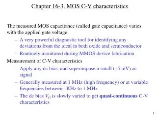
Chapter 16-2. MOS electrostatic: Quantitative analysis
Chapter 16-2. MOS electrostatic: Quantitative analysis. In this class, we will Derive analytical expressions for the charge density, electric field and the electrostatic potential. Expression for the depletion layer width Describe delta depletion solution Derive gate voltage relationship

Chapter 16-2. MOS electrostatic: Quantitative analysis
E N D
Presentation Transcript
Chapter 16-2. MOS electrostatic: Quantitative analysis • In this class, we will • Derive analytical expressions for the charge density, electric field and the electrostatic potential. • Expression for the depletion layer width • Describe delta depletion solution • Derive gate voltage relationship • Gate voltage required to obtain inversion
Electrostatic potential, (x) Define a new term, (x) taken to be the potential inside the semiconductor at a given pointx. [The symbol instead of V used in MOS work to avoid confusion with externally applied voltage, V] Potential at any point x Surface potential | F | related to doping concentration F> 0 means p-typeF< 0 means n-type
Electrostatic parameters S is positive if the band bends downward S = 2F at the depletion-inversion transition point
EC Ei EF EV 12kT Example 1 Consider the following F and S parameters. Indicate whether the semiconductor is p-type or n-type, specify the biasing condition, and draw the energy band diagram at the biasing condition. (i) F = 12 kT/q; S = 12 kT/q F = +12kT/q means that Ei – EF in the semiconductor is 12 kT (a positive value); So, p-type. NA = ni exp [(Ei – EF ) / kT] S=12 kT/q means Ei (bulk) – Ei(surface) = 12 kT; i.e. the band bends downward near the surface.
EC EF Ei EV -9kT Example 1 (continued) (ii) F = 9 kT/q; S = 18 kT/q here F = 9 kT/q means [Ei(bulk) – EF] = 9 kT; i.e., Ei is below EF. Thus the semiconductor is n-type. S= 18 kT/q means that Ei (bulk) – Ei(surface) = –18 kT; So band bends upwards near the surface. The surface is “inverted” since the surface has the same number of holes as the bulk has electrons.
p-Si VG < 0 Accumulation of holes Delta-depletion solution M O S Consider p-type silicon Accumulation condition The accumulation charges are mobile holes, and appear close to the surface and fall-off rapidly as x increases. Assume that the free carrier concentration at the oxide-semiconductor interface is a -function. x Charge on metal = QM Charge on semiconductor = (charge on metal) |QAccumulation| = |QM|
M O S p-Si VG > 0 QM w Depletion of holes Delta depletion solution (cont.) Consider p-type Si, depletion condition Apply VG such that s < 2 F Charges in Si are immobile ions - results in depletion layer similar to that in pn junction or Schottky diode. |q NA A W| = |QM| () (+) If surface potential is s (with respect to the bulk), then the depletion layer width W will be E ESi dE/dx = qNA/si x At the start of inversion, s = 2F and
Depletion layer width, W and E-field For a p+n junction, or a MS (n-Si) junction, the depletion layer width is given by: Where Vbi is related to the amount of band bending. Vbi in Volts is numerically equal to the amount of band bending in eV. For MOS, the same equation applies, except that Vbi is replaced by s. n-type p-type
M O S p-Si VG>>0 Delta depletion solution (cont.) Consider p-Si, strong inversion. Once inversion charges appear, they remain close to the surface since they are mobile. Any additional voltage to the gate results in extra QM in gate and get compensated by extra inversion electrons in semiconductor. w QM Depletion of holes Inversion electrons: -function-like So, depletion layer does not have to increase to balance the charge on the metal. Electrons appear as -function near the surface. Maximum depletion layer width W = WT
M O S p-Si VG > 0 Gate voltage relationship Applied gate voltage will be equal to the voltage across the oxide plus the voltage across the semiconductor. Consider p-type Si. VG= ox +Semi Semi = (x = 0) (bulk) = S ox = xoxEox ox Semi Since the interface does not have any charges up to inversion, we can say that oxEox = SiESi Eox = (Si / ox) ESi
Gate-voltage relationship (Alternative method) Consider p-type silicon VG= ox+ Semi ox= QM/Cox = Qs/Cox where Cox is oxide capacitance and Qs is the depletion layer charge in semiconductor Qs = q A NAW Cox = ox A / xox (same as before)