Error Resilience in MPEG-4: Techniques and Tools for Robust Video Streaming
This paper discusses the critical tools for error resilience in MPEG-4 environments, focusing on three primary categories: resynchronization, data partitioning, and data recovery. It elaborates on resynchronization techniques, including VOP start codes and fixed interval synchronization to isolate errors effectively. The significance of data partitioning to separate motion data from texture is also highlighted, along with methods for recovery, such as RVLC and shape coding. These strategies ensure reliable video object transmission and enhance the integrity of multimedia content in MPEG-4.

Error Resilience in MPEG-4: Techniques and Tools for Robust Video Streaming
E N D
Presentation Transcript
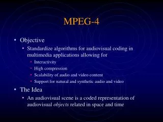
Error Resilience for MPEG-4 Environment Nimrod Peleg Nov. 2000.
MPEG-4 Error Resilience Tools Three major categories: • Resynchronization • Data Partitioning • Data recovery • Extended header codes • RVLC • Error concealment
MPEG-4 Error Resilience Tools (2) Resynchronization, Data partitioning, RVLC
MPEG-4 Resynchronization (1) • Usually, data between 1st sync. And 2nd sync. (error in between) is discarded. • Resync. Should localize errors a help recovery by other methods • As in MPEG-2 adaptive slice and H.263 Slice Structure Mode - MPEG-4 insers periodical resync. Markers along the bitstream. • The length of a video packet is not based on the number of MB, but on the bits contained in that packet
MPEG-4 Resynchronization (2) • If the number of bits in a video packet is too large, a new packet is created at the start of the next MB. • Resync. Marker is called: “VOP start code” • Another option: ‘fixed interval sync.’ : • VOP start codes and resync. Markers appear only at fixed legal interval locations in the bitstream. • The decoder is only required to search for VOP start code at the beginning of of each fixed interval • (helps to avoid problems associated with start code emulation)
Resync. Marker MB Address QP HEC Motion/ Header/ (shape) Motion Marker Texture Data Resync. Marker MPEG-4 Data Partitioning • Separating motion and MB header data from the texture data. • If shape data exists, it is also partition (see later)
Resync. Marker MB Address QP HEC Forward Decode Errors Backward Decode Resync. Marker MPEG-4 Data Recovery • Once data is lost, a set of tools to ‘recover’ is available: • RVLC
Shape Coding in MPEG-4 • MPEG-4 uniqueness: arbitrary shaped Video Objects (VOs) • VOP (Plane): a frame consists of VOs. • MPEG-4 works in object-based approach: texture, motion and shape data of one VO are placed in one bitstream. • Several VOs are multiplexed together to form a frame, scene etc.
Alpha-Map • A shape of an object is defined by an Alpha-map: for each pixel it is determined whether it belongs to the VO or not: • Alpha - Value > 0 : belongs to VO • Alpha - Value = 0 : Does not belong • Opaque objects: Value=255 • Transparent objects: 1 < Value < 254 For binary shapes: Alpha - Value = 0 : background Alpha - Value = 255: object
Binary Shape Encoding • For binary shapes, shape information is divided into 16x16 Binary Alpha Blocks (BAB). • BAB may contain any combination of transparent or opaque objects. • Completely opaque/transparent blocks are signed at the MB level.
“Mixed” Blocks • 5 additional modes for mixed blocks encoding, utilizing a combination of motion compensation and Context-basedArithmetic Encoding (CAE). • The 5 modes are signaled using a VLC which is dependent on the coding mode of the surrounding MB’s , and they are: • 1. no MV, no shape update • 2. no MV, shape update (Inter CAE) • 3. MV, no shape update • 4. MV, shape update (Inter CAE) • 5. Intra Shape (Intra CAE)
x x x x x x x x x x o “Mixed” Blocks Modes • Intra-Mode: • MB is processed in scan-line order. • A template of 10 pixels is used to define a context for the shape value at the current location: The context depends on the current MB and previously decoded shape information (if unknown: set to the closest value within the MB) Once the context is computed, the probability that the location is transparent (or opaque) is determined, using a lookup table, which is defined by MPEG-4 spec., with 1024 possible contexts. The block is coded using the derived probabilities and Arith. coding
“Mixed” Blocks Modes Cont’d • Inter-Mode • 4 additional modes (1-4, above) appear in predicted VOPs (P,B, Sprite with global ME) • MC is used to provide initial estimate of the BAB • Estimation of the MV is derived from the neighboring MVs, and if there is differential value (sent by the encoder) it is added. • Binary shape information is extracted from the reference VOP, using pixel accurate motion compensation.
x x x x x Inter-Mode cont’d • If the encoder signals the presence of an arithmetic code, binary shape info. is sent with an Inter-VOP CAE. The Inter VOP template contains 9 pixel values: 4 in the current BAB and 5 from the reference VOP. (undefined pixels are set as the closest value with in the MB. x x x x o Current Frame Previous Frame Arithmetic code is derived using probabilities specified for each of the 512 contexts.
Lossy Encoding • In addition to coding mode at the encoder, another information is specified to control quality and bit-rate of binary shape information: • MB can be encoded at reduced resolution by two or four, resulting 8x8 or 4x4 BABs, encoded at one of the above mentioned modes. • The reduced resolution BAB is up-sampled using adaptive filter. The filter relies on the 9 pixels surrounding the low-resolution shape value.
Spatial-Scalability • Two other options can effect bit-rate and quality: • Efficiency of CAE depends on the orientation of the shape info. To increase it, the encoder can ‘transpose’ the BAB before encoding. • Spatial scalability is optional (MPEG-4 ver.2): the base layer is decoded as described before, the enhancement layer refines the shape information of the base layer. • High resolution block is predicted from either low-resolution data at the same time instant, or higher resolution data in previously enhanced VOPs.
Gray-Level Shape Data • After the Binary Shape Data is encoded, the gray-level shape datascan be sent as transparency values. • Every four 8x8 blocks (BAB) are encoded together, using same MV data from the luminance channel • only slight difference: no overlapped MC
Gray-Level Shape Data (cont’d) Two extensions in MPEG-4 ver. 2: • A bit-stream may contain and up to 3 channels ofgray-level shape data (Transparency). • Any combination of transparency, depth, disparity and texture is allowed. • Shape Adaptive DCT incorporates the binary shape data into DCT calculation (of luminance)
Shape Error Resilience (1): Pixel Location • When “error resilience mode” is enabled, modifications in the shape encoder reduce the sensitivity to channel errors, in the stage of CAE computation. • The context of CAE is redefined by denoting any pixel location that is external to the current video packet as transparent. • This limits error propagation (for both inter and intra CAE modes)
SER (2): Data Partitioning • Another option: Data partitioning: • MB header, binary shape information and MV data are separated from texture information. • A special marker (resynchronization) is inserted between the two components. • Two advantages: • Error in shape data does not affect shape data • Unequal error protection is enabled: more protection for MV and shape data.
Data Partitioning (cont’d) • Data partitioning is possible only for binary shape data • For gray-level shape information it is not defined, so unequal error protection is unavailable. • It also disables the option of RVLC for DCT coefficients, so an error forces us to discard the whole package.
SER (3): Video packet header • This header can be inserted periodically, as resynchronization sign (start of MB). • It also includes redundant information from the VOP header: VOP can be decoded even if its header is corrupted ! • This is true only when no shape data exists… • in the former case, VOP header includes size and spatial location of the shape (which are not included in video packet header)
Further reading • Yao Wang et al. “Error Resilient Video Coding Techniques”, IEEE Signal Processing Magazine, July 2000