Download
1 / 35
350 likes | 599 Views
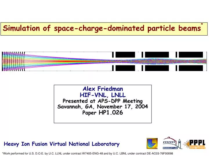
Simulation of space-charge-dominated particle beams *. Alex Friedman HIF-VNL, LNLL Presented at APS-DPP Meeting Savannah, GA, November 17, 2004 Paper HP1.026. Heavy Ion Fusion Virtual National Laboratory.

E N D
Simulation of space-charge-dominated particle beams* Alex Friedman HIF-VNL, LNLL Presented at APS-DPP Meeting Savannah, GA, November 17, 2004 Paper HP1.026 Heavy Ion Fusion Virtual National Laboratory *Work performed for U.S. D.O.E. by U.C. LLNL under contract W7405-ENG-48 and by U.C. LBNL under contract DE-AC03-76F00098
Simulation plays a major role in developing the answers Key question in Heavy Ion Fusion beam science:How do intense ion beams behave as they are accelerated and compressed into a small volume in space and time? Outline: • Introduction • Present-day experiments • Fundamental beam science • Future experiments & discussion … and along the way … New computational methods and models with broad applicability
beam ions background ions electrons target Beams are non-neutral plasmas with dynamics dominated by long-range space-charge forces They are collisionless and have “long memories” — must follow ion distribution from source to target Beam modeling program is ~ 2/3 simulation, ~ 1/3 analytic theory; here we discuss the former “Multiscale, multispecies, multiphysics” - ions encounter: • Good electrons: neutralization by plasma aids compression, focusing • Bad electrons: stray “electron cloud” and gas can afflict beam
In driver -12 -11 -10 -9 -8 -7 -6 -5 -4 -3 -2 -1 0 Length scales: • electron gyroradius in magnet ~ 10 mm • lD,beam ~ mm • beam radius ~ cm • lattice period ~ m • beam length ~ 1-10 m • machine length ~ km In chamber Time & length scales in driver&chamberspan a wide range Time scales: depressed betatron betatron t electron drift pb out of magnet » transit lattice thru electron period fringe beam cyclotron pulse fields residence in magnet log of timescale (s) pulse beam t pe residence t pi t pb
Beam starts with a small 6D phase space volume; applications demand that it grow only modestly • Present-day (e.g., “HCX”) beams, roughly: • Total ions N ~ 5 x 10¹² (K+) in ~ 5 ms (0.2 Amperes) • line charge density ~ 0.1 C/m • number density n ~ 1015 m-3 • kinetic energy Ek ~ 1 MeV (v/c ~ 0.005) • temperature Teff ~ 0.2 eV at 5-cm source, ~ 20 eV in transport section • beam radius r ~ 1 cm • T and r translate to initial transverse phase space area (“normalized emittance”) ~ 0.5 -mm-mr • Example: at the downstream end of a 2-GeV system: • increases ~ 5x in accelerator, then 20x in final compression • Have “headroom” for phase space area to grow by ~ factor of 10 (less is always better)
Particle-in-Cell (PIC) is main tool; challenges are addressed by new computational capabilities • resolution challenges (Adaptive Mesh Refinement-PIC) • dense plasmas (implicit, hybrid PIC+fluid) • short electron timescales (large-Dt advance) • electron-cloud & gas interactions (new “roadmap”) • slowly growing instabilities (f for beams) • beam halo (advanced Vlasov)
Track beam ions consistently along entire system Ion source & injector Accelerator Buncher Final focus Chamber transport Target HIF-VNL’s approach to self-consistent beam simulation (HEDP & IFE) employs multiple tools Study instabilities, halo, electrons, ..., via coupled detailed models
Research on high-brightness sources & injectors uses “test stands” II. Simulations and theory support present-day ion beam experiments Injector physics STS-500 at LLNL
Fine grid patch around source & tracking beam edge high resolution low resolution + AMR 0.4 0.2 0.0 0.1 0.2 0.3 0.4 WARP simulations of HCX triode illustrate the integration of particle-in-cell (PIC) & adaptive mesh refinement (AMR) methods Application to HCX triode in axisymmetric (r,z) geometry r This example: ~ 4x savings in computational cost (in other cases, far greater savings) z (m) eN (p-mm.mrad) Z (m) (Simulations by J-L. Vay)
Adaptive Mesh Refinement requires automatic generation of nested meshes with “guard” regions Simulation of diode using merged Adaptive Mesh Refinement & PIC
Phase space at end of diode Warp simulation Experimental data Experiment 10 Theory x -10 -50 0 50 -50 0 50 x (mm) x (mm) (Simulations by I. Haber, J-L. Vay, D. P. Grote) WARP simulations of STS-500 experiments clarify our understanding of short-rise-time beam generation Rise time Current (mA) at Faraday cup 6 4 2 0 0 2 4 time (s) Result depends critically on mesh refinement 5-cm-radius K+ alumino-silicate source
7.5 X (mm) -7.5 0.5 1.0 0. 1.5 Z (m) Einzel lens plates Free drift Novel compact injector, based on merging of many bright beamlets, is being studied • Now: high-gradient experiment with parallel beamlets Simulation Experiment y (m) x (m) J. Kwan poster Monday PM described this work • Soon: “curved-plate” exp’t: • 119 beamlets, 0.07 A total, 400 keV
HCX ESQ injector Marx 10 Electrostatic quads ESQ injector 4 Magnetic quads matching diagnostics 10 ES quads diagnostics diagnostics The High Current Experiment enables studies of beam dynamics and stray-electron physics K+ Beam ~ 0.2 - 0.5 A 1 - 1.7 MeV ~ 5 s
Time-dependent 3D simulations of HCX electrostatic quadrupole injector reveal beam-head behavior From a WARP movie by J-L. Vay; see http://hif.lbl.gov/theory/simulation_movies.html Much recent HCX work has focused on electron-cloud; see below
y v Slit Scintillator u x Isosurface upon which ƒ(x,y,x) = 0.3 ƒmax shadow of “bridge” across slit face-on (xy) view rotated to right “Optical slit” diagnostic is yielding unprecedented information about the HCX beam particle distribution • This scanner measures f(x,y,x) • Another such scanner at right angles measures f(x,y,y) • Using both, suitably remapped to a common longitudinal plane, one can tomographically “synthesize” an approximation to the 4-D f(x,y,x,y) • Ref: A. Friedman et al., PAC 2003: • http://accelconf.web.cern.ch/accelconf/p03/PAPERS/TOPB006.PDF C. M. Celata poster CP1.119 (Monday afternoon) showed use of such a “synthesized” 4-D f as initial conditions for PIC simulations
NTX The Neutralized Transport Experiment (NTX) enables studies of beam neutralization and focusing 4 magnetic quadrupoles MEVVA source (plasma plug) Non-neutralized FWHM = 6.6 mm Plasma plug + volume plasma RF source (volumetric) Scintillating glass diagnostic FWHM = 1.5 mm
Slit-integrated intensity Slit-integrated intensity After 4 magnetic focusing quads, data & WARP-generated density profiles agree well, except for halo (which originated upstream) 1.5 mA beam Horizontal density profile 265keV Vertical Horizontal 283keV Vertical
With plasma plug MEASUREMENT SIMULATION 1.3 1.7 mm 7 mm LSP simulations of NTX agree with data at focal plane for different neutralization methods (within error bars) With plasma plug and RF Plasma “No space charge” DATA MEASUREMENT MEASUREMENT SIMULATION SIMULATION 1.0 mm (radius containing half the current) 1.4 mm 0.8 1.1 • EM, 3D cylindrical geom., 8 azimuthal spokes • 3 eV plug 3x109 cm-3, volume plasma 1010 cm-3 • 6 mA, 10 mm initial radius LSP Linear color scale Carsten Thoma, et al.
Q3 Q1 Q4 UMER University of Maryland Electron Ring will study long-path transport physics Experiment WARP The rings are due to edge lensing
Electron lifetime ~ time to drift out the end of a magnetic quadrupole Electrons can trap into beam space-charge and quadrupole magnetic fields Gas, electron source diagnostic for number and energy of electrons and gas molecules produced per incident ion Beam Tiltable target III. Fundamental beam science studies: “afflictions and avoidance thereof” Experiments and simulations explore sources, sinks, and dynamics of stray electrons electron cloud quad beam R. Cohen inv. talk Wed. AM & poster Wed. PM A. Molvik’s poster Tues. AM
fb,wall WARP ion PIC, I/O, field solve fbeam, F, geom. Reflected ions gas module fb,wall penetration from walls ambient nb, vb ions fb,wall volumetric (ionization) electron source wall electron source charge exch. ioniz. F electron dynamics (full orbit; drift) sinks ne We are following a road map toward self-consistent e-cloud and gas modeling in WARP Key: operational; implemented and undergoing testing; partially implemented;active offline development
Self-consistent WARP3d simulations of electrons and ions in 4th HCX magnet help validate large-t electron mover new mover, t 10x larger Boris/Parker-Birdsall small t ions
Instabilities Nonlinear df simulations reveal properties of electrostatic anisotropy-driven mode • When T > T, free energy is available for a Harris-like instability • Earlier work (1990 …) used WARP • Simulations using BEST df model (above) show that the mode saturates quasilinearly before equipartitioning; final v v / 3 • BEST was also applied to Weibel; that mode appears unimportant for energy isotropization • BEST, LSP, and WARP are being applied to 2-stream
px 10-5 10-4 10-3 10-2 10-1 1 x Halo Solution of Vlasov equation on a grid in phase space offers low noise, large dynamic range • 4D Vlasov testbed (with constant focusing) showed halo structure down to extremely low densities Evolved state of density-mismatched axisymmetric thermal beam with tune depression 0.5, showing halo
New ideas include moving grid in phase space to model quadrupoles, adaptive mesh to resolve fine structures moving phase-space grid, based on non-split semi-Lagrangian advance adaptive mesh in phase space
IV. Simulations enable exploration of future experiments HI-driven IFE will require matter in the “High Energy Density Physics” (HEDP) regime; ion-driven strongly-coupled 1-eV plasmas (“Warm Dense Matter”) will come first • HEDP regime is > 1011J/m3 (NRC) • Must produce the beam, compress it longitudinally, focus it • Approach for “Neutralized Drift Compression Experiments”: • “Accel-decel” or other short-pulse injector • Neutralization to allow drift compression in short distance • Final focusing system with large chromatic acceptance NDCX J. Barnard poster Monday afternoon covered this in detail
Ion beam Strategy: maximize uniformity and efficient use of beam energy by placing center of foil at Bragg peak In simplest example, beam impinges on a foil of solid or “foam” metal Example beam: He+, 10 A, 2 MeV, rspot = 1 mm, p<< 1 ns (pulse duration << hydrodynamic disassembly time) Energy loss rate DdE/dX DT log-log plot fractional energy loss can be high and uniformity also high if operating at Bragg peak (Larry Grisham, PPPL) (MeV/mg cm2) Enter foil Exit foil (dE/dX figure from L.C Northcliffe and R.F.Schilling, Nuclear Data Tables, A7, 233 (1970)) Energy/Ion mass (MeV/amu)
NDCX-1 has 3 stages over next ~2 years; will study neutralized compression by factors of 10-100 1a - Neut. Drift Compr.; starting ~ now 1b - solenoid transport; start June 05 1c - accel-decel / load & fire; start Oct. 05
Accel. Solenoid column transport Gun WARP simulation of a novel high line charge density injector based on the accel-decel / load-and-fire principle
LSP simulations of neutralized drift and focusing show possibility of strong compression in NDCX-1 • As simulated: • Axial compression 120 X • Radial compression to 1/e focal spot radius < 1 mm • Beam intensity on target increases by 50,000 X. R(cm) Z(cm) 3.9T solenoid Ramped 220-390 keV, K+, 24 mA ion beam injected into a 1.4-m long plasma column with density 10 x beam density. (simulations by Welch, Rose, Henestroza, Yu)
EDPIC simulation of ion pulse neutralization: waves induced in plasma are modified by a uniform axial magnetic field electron density contours ne/np electron flow past beam 2D EM PIC code in XY slab geometry, comoving frame, beam & plasma ions fixed Analytic theory & simulation by Igor Kaganovich x (c/p) vb = c/2; lb = 7.5 c/p; c=5p; rb = 1.5 c/p; nb = np/2 y (c/p)
C L NDCX experiments may employ a novel accelerating method based on broadband Traveling Wave Accelerator Accel-decel injector with “load-and-fire” column Broadband Traveling Wave Accelerator Energy ramping Neutralized Drift Compression • Traveling Wave Accelerator is based on slow-wave structure (helix) • Beam “surfs” on traveling pulse of Ez (moving at ~ 0.01 c in first stage) • One possible configuration: Vs(t) from Pulse Forming Network 3-D FDTD calculations of EM pulse propagation are underway (S. Nelson) Insulator column ion pulse
Knowledge gained on NDCX-1 and on bench tests of slow-wave structures opens up new NDCX-2 opportunity • Adds helical line to NDCX-1 (still uses K+) • 20 MeV < Bragg peak (~ 50 MeV), but deposition only down ~10-15% • ~ 8 meters long, < $2M for full 5 T solenoid system • Rbeam = 2 cm, ahelix = 4 cm, bwall = 10 cm • +/- 450 kV drive (not all usable for beam) • Beam 15-20 cm • Voltage ramps over 30 cm acceleration at 3 MV/m • 3 helix segments, each w/ tapered line tracking ~2x gain in velocity • Longitudinal blow-up controlled by “tilt” and “inertia” (rapid accel) • Target heating to ~ 1eV if focus to rspot < ~ 1 mm
Discussion Program needs drive us toward “multiscale, multispecies, multiphysics” modeling • e-Cloud and Gas: • merging capabilities of WARP and POSINST; adding new models • new method for bridging disparate e & i timescales • Plasma interactions: • LSP already implicit, hybrid, with collisions, ionization, … now with improved one-pass implicit EM solver • Darwin model development (W. Lee et. al.; Sonnendrucker) • Injectors • Merging beamlet approach is “multiscale” • Plasma-based sources (FAR-Tech SBIR) • New HEDP mission changes path to IFE; models must evolve too • Non-stagnating pulse compression • Plasmas early and often • Modular approach a natural complement
Closing thoughts … While simulations for Heavy Ion Fusion are at the forefront in terms of the relative strength of the space charge forces, a wide range of beam applications are pushing for higher intensity, and will benefit from this work MFE applications may also benefit from AMR-PIC, Vlasov, e-mover, … This talk drew on material from quite a few people - thanks to all!