Download
1 / 18
190 likes | 326 Views
Explore the Wheatstone Bridge, a null-measurement method for precise resistance evaluation. Learn about its derivation, operation, and applications in resistance measurements.

E N D
Dynamic Presentation of Key Concepts Module 2 – Part 4The Wheatstone Bridge Filename: DPKC_Mod02_Part04.ppt
Overview of this PartThe Wheatstone Bridge In this part of Module 2, we will cover the following topics: • Null Measurement Techniques • Wheatstone Bridge Derivation • Wheatstone Bridge Measurements
Textbook Coverage This material is introduced in different ways in different textbooks. Approximately this same material is covered in your textbook in the following sections: • Circuits by Carlson: Section 3.5 • Electric Circuits 6th Ed. by Nilsson and Riedel: Section 3.6 • Basic Engineering Circuit Analysis 6th Ed. by Irwin and Wu: Section 2.8 • Fundamentals of Electric Circuits by Alexander and Sadiku: Section 4.10.2 • Introduction to Electric Circuits 2nd Ed. by Dorf: Not covered
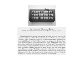
The Wheatstone Bridge – A Null-Measurement Technique The subject of this part of Module 2 is the Wheatstone Bridge, a null-measurement technique for measuring resistance. There are also null-measurement techniques for measurements of things like voltage, but we will just consider this one example to illustrate the principle. These techniques have the following properties: • They use a standard meter, such as an ammeter or voltmeter. • The measurement occurs when the reading on this ammeter or voltmeter is zero.
Null-Measurement Techniques – Note 1 Null-measurement techniques use a standard meter, such as an ammeter or voltmeter. Typically, they use an analog meter, such as the D’Arsonval meter movement, which is described in many circuits textbooks. Such meters are sometimes thought of as ammeters, since their response is due to the magnetic field in a coil, caused by a current. However, since these meters can be modeled as resistances, which means that the current through them is proportional to the voltage across them, the distinction is not really important. In this sense, all of these meters are both voltmeters and ammeters.
Null-Measurement Techniques – Note 2 The null-measurement occurs when the reading on this ammeter or voltmeter is zero. This is a huge practical benefit. Making a meter which is precisely linear, with an accurate scale, and negligible resistance, is a challenge. None of these issue matter in a null measurement, since the purpose of the meter to determine the presence or absence of current or voltage. It does not need to be linear; it is only important to detect the zero value. The resistance does not matter, since there is no current through the meter at the point of measurement. The only concern is that the meter be able to detect fairly small currents, during the nulling step. This makes the design much easier.
Null-Measurement Techniques – Note 3 We will consider the particular null-measurement technique known as the Wheatstone Bridge. This is a very accurate resistance measurement technique, which also has applications in measurement devices such as strain gauges. There are other null-measurement techniques. One such technique is called the Potentiometric Voltage Measurement System. This is discussed in the textbook Circuits, by A. Bruce Carlson, on pages 121 and 122. A diagram from the text is included here. While interesting, we will concentrate on the Wheatstone Bridge in this module.
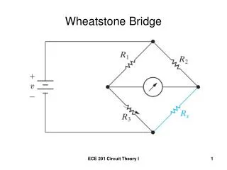
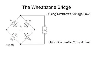
The Wheatstone Bridge The Wheatstone Bridge is a resistance measuring technique that uses a meter to detect when the voltage across that meter is zero. The meter is placed across the middle of two resistor pairs. The resistor pairs in the circuit here are R1 and R3, and R2 and RX. The meter is said to “bridge” the midpoints of these two pairs of resistors, which is where the name comes from. A source (vS) is used to power the entire combination. See the diagram here.
Go back to Overview slide. The Wheatstone Bridge – Notes The resistor RX is an unknown resistor, that is, the resistor whose resistance is being measured. The other three resistors are known values. The resistor R3 is a variable resistor, calibrated so that as it is varied its value is known. The meter is conceptually a voltmeter. However, it should be noted that a meter is a resistor from a circuits standpoint, so that when the voltage is zero the current is also zero.
The Wheatstone Bridge – The Nulling Step To make the measurement, the resistor R3 is a varied so that the voltmeter reads zero. Thus, when R3 is the proper value, then vM and iM are both zero.
The Wheatstone Bridge – Derivation Step 1 Using the fact that vM and iM are both zero, we can derive the operating equation for the Wheatstone Bridge. Let’s take this derivation one step at a time. First, since iM is zero, we can say that R1 and R3 are in series, and R2 and RX are in series.
The Wheatstone Bridge – Derivation Step 2 Second, since R1 and R3 are in series, and R2 and RX are in series, we can write expressions for v3 and vX using the voltage divider rule,
The Wheatstone Bridge – Derivation Step 3 Third, since vM is zero, we can write KVL around the loop and show that v3 is equal to vX. Thus, we can set the expressions for these two voltages equal,
Go back to Overview slide. The Wheatstone Bridge – Derivation Step 4 Fourth, we can divide through by vS. This is important, since it means that the exact value of vS does not matter. For example, the source could be a battery, and if the battery runs down a little, it does not change the measurement. We get,
The Wheatstone Bridge – Equation So, we have shown that when R3 is adjusted so that meter reads zero, this results in the equation below. Since R1, R2, and R3 are known, we now know RX.
The Wheatstone Bridge – Measurements Let’s review the basics of the Wheatstone Bridge. • The resistors R1, R2, and R3 are known, and R3 is variable. • The resistor R3 is varied until the meter reads zero. • Because the meter reads zero, the current through it is zero, leaving two series resistor pairs. • Because the meter reads zero, the voltage across it is zero, making the voltage divider rule voltages equal. • Setting these voltages equal and solving yields the equation below.
Go back to Overview slide. The Wheatstone Bridge – Operating Notes Let’s review the advantages of the Wheatstone Bridge. • The accuracy of the measurement is determined almost entirely by the accuracy of the values of the resistors R1, R2, and R3. Typically, it is relatively easy to have these resistances accurately known. • The meter reads zero during the measurement, so the linearity, accuracy and resistance of the meter do not matter. The meter only needs to detect the point at which the voltage across it is zero. At this point the bridge is said to be “balanced”. • The source voltage term cancels, so if vS changes, the accuracy of the measurement is not seriously affected. The voltage vS only needs to be large enough to deflect the meter when the bridge is not “balanced”.
What’s So Special About Null-Measurement Techniques? • Null-Measurement Techniques are a clever way of using the strengths of meters, particularly analog meters, while minimizing their weaknesses. As such, they are a good example of problem-solving approaches. • In addition, these techniques allow us to exercise the concepts covered earlier in the module, such as series resistors and the voltage divider rule. Go back to Overview slide.