Download
1 / 25
250 likes | 502 Views
ELQA Campaigns for SMACC. TE/MPE/EE. LHC Machine. CONTRIBUTIONS BY ELQA prior to / during / at the end of LS1 Presentation to the 3 rd LHC Splice Review 12-14 November 2012

E N D
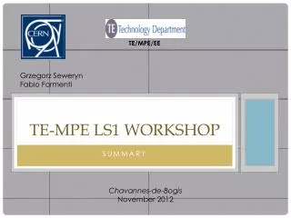
ELQA Campaigns for SMACC TE/MPE/EE LHC Machine CONTRIBUTIONS BY ELQA prior to / during/at the end of LS1 Presentation to the 3rd LHC Splice Review 12-14 November 2012 by K. Dahlerup-Petersen -on behalf of the complete ELQA team: M.Bednarek, G. D’Angelo, R. Mompo, G. Seweryn, S. Pemberton, M. Dominguez-Martinez, E. Nowak, P. Dubert, R. Kulaga and K. Pereira. K. Dahlerup-Petersen TE/MPE/EE – 5 November 2012
ELQA Campaigns for SMACC TE/MPE/EE LHC Machine • Agenda: • General overview of Electrical Quality Assurance Activities related to LS1 • PAQ - objectives for the SMACC-related ELQA campaign • Details of a Partial Assembly Qualification with respect toLS1 • For synchronized follow-up of the busbar consolidation • For replacement of 15 + 4 main cryo magnets • Safety aspects. • Short presentation of the new TP4 measurement system. • The AIV procedure. • Resources: Equipment and Manpower. • Human resources related to the LS1 ELQA campaigns. • Revision of HVQ test voltages: • Motivation for applying changes • The new values • Conclusion • The new, distributed voltage-to-ground monitor: Can it be used for early detection of weak insulation points? K. Dahlerup-Petersen TE/MPE/EE – 5 November 2012
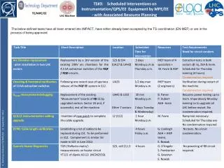
ELQA Campaigns for SMACC TE/MPE/EE LHC Machine • Electrical Quality Assurance is required in basically all phases of the LS1project: • @ COLD @ THE END OF 2012-13 LHC OPERATION: • 1) Verification & Consolidation of non-conformities of different origins in circuitry and • components - during the period of Powering Tests • quenches at low current, open circuits, shorts, low voltage withstand, missing magnets • - 10 cases in 5/ 8 LHC sectors to be investigated/cured • 2) ELQA Standard Campaign TP4 E- with new HV parameters and cryoinstr. disconnected • incl. the MIC-C & DOC-C tests • - TP4 E complete Q.A. verification @ cold (incl. transfer function and H.V.) • - MIC-C individual magnet checks, incl. resistance measurements and H.V. test • of coil, busbars and all quench heater circuits ( 6’000 units) @ cold • - DOC-C resistance measurements of coil, transfer function, H.V. and instrumentation • on all dipole orbit corrector circuits @ cold • All this according to the updated test procedures – EDMS doc. 788197 –rev. 1.2 (April 2012) • DURING WARM-UP: • - Continuous checking of short-circuits to ground (ELQA) and broken voltage taps (QPS) • QPS/ELQA ACTIVITIES @ WARM PRIOR TO THE SPLICE CONSOLIDATION: • ELQA Standard Campaign TP4 A+B incl. MIC-W and DOC-W • 2) Resistance measurements of all interconnecting busbar segments with 5-30 A – • 200 V powering , - use of mDQQBS boards and nQPS data handling. • On the 3 Main circuits in all 8 sectors (2 sectors/day in average) K. Dahlerup-Petersen TE/MPE/EE – 5 November 2012
ELQA Campaigns for SMACC TE/MPE/EE LHC Machine • Electrical Quality Verification during LS1 (contd.) • ELQA ACTIVITIES DURING LS1: • 1) AIV (Arc Interconnection Verification ) applied for magnet replacement • -concerns all Spoolcircuits and all N-linecircuits: integrity, polarity and HV tests • 2) PAQ (Partial Assembly Qualification) for Main busbarsand Spool circuits: electrical • continuity proof (Spools) and H.V. Qualification (Mains & Spools) – related to SMACC • - Non-conformity follow-up. • - Test Procedures: AIV unchanged, PAQ updated with specific requirements for LS1. • See next slides • @ WARM AFTER COMPLETION OF THE SPLICE CONSOLIDATION AND THE • REPLACEMENT OF 19 CRYO MAGNETS: • 1) Complete ELQA Standard Campaign TP4 A & B, MIC-W, DOC-W • 2) Repetition of the warm resistance measurements of all interconnecting busbar segments • with 5-30 A powering - identical to the exercise made before the LS1 interventions. • DURING COOL-DOWN: • TP4 C and QPS continuous monitoring of possible short-circuits and integrity of the voltage • tap connections • @ COLD - PRIOR TO POWERING FOR HARDWARE COMMISSIONING: • Complete ELQA campaign TP4 E, MIC-C, DOC-C - based on the updated procedure K. Dahlerup-Petersen TE/MPE/EE – 5 November 2012
ELQA Campaigns for SMACC TE/MPE/EE LHC Machine Particular emphasis on the ELQA Follow-up of the MSC Splice Consolidation ‘Train’: Objective: To assure a prompt verification of the relevant electrical and di-electrical properties of the dc powering circuits contained in the M1, M2 and M3 lines, i.e. the three main powering circuits and the spools, during the consolidation period. This added value is provided through a daily (nightly!) ELQA campaign (PAQ) of circuit verifications, on-line transmission of the test results and collection of a maximum of information for facilitating localization and correction of disclosed non-conformities. K. Dahlerup-Petersen TE/MPE/EE – 5 November 2012
ELQA Campaigns for SMACC TE/MPE/EE LHC Machine • The PAQ test • -Two-step procedure introduced during the initial installation and connection • of the LHC for application to M1, M2 & M3 Main busbars and M1, M2 spool • conductors. One TP4 mobile test bench is used per PAQ test. • -Set of electrical testsapplied to a powering segment, originally corresponding • to one half-cell (3 or 2 (DS) dipoles + 1 SSS), however, other segments can • be defined and treated. • -Procedure now adapted to the particular conditions of the less systematic • splice consolidation work of LS1 and documented in the document • ‘LS1 PAQ Test Procedure’ (soon on EDMS). H.V. test voltage will be 500 Vdc. • -Required temporary conditions to allow correct application of the PAQ • procedure: • 1) Disconnection of the warm DC cables & the instrumentation cables @ • the level of the DFB/CL’s • 2) Temporary interruption of each of the 2 x 10 Spool piece busbars @ • an interconnection close to the odd-point end of the chain. • 3) Temporary removal of the conductor insulation from the RB, RQF, RQD • busbars @ the same magnet interconnection. K. Dahlerup-Petersen TE/MPE/EE – 5 November 2012
ELQA Campaigns for SMACC TE/MPE/EE LHC Machine • The PAQ test (contd) • -The places of temporary spool rupture and Main busbar insulation removal • have been coordinated with MSC-group so to minimize impact: • Point 1 & 5 left and right: The IC corresponds to the place of RQF/RQD busbar • shortening. NOTE: It is not necessary to check ‘upstream’ of this point as there • will be no risk of damage as no repair work there. • Point 3 right: The IC is at the Q7 quad which is listed for replacement. • In the remaining points (P7 left and right as well as P3 left) the open place • is also near Q7 or Q8. K. Dahlerup-Petersen TE/MPE/EE – 5 November 2012
ELQA Campaigns for SMACC TE/MPE/EE LHC Machine K. Dahlerup-Petersen TE/MPE/EE – 5 November 2012 • Other requirements: • - At all points undergoing repair work all busbars must be individually insulated wrt • each other and to ground at the moment (17H00 daily) when the ELQA team takes • over the sector. • Only exceptions are the points in the above table, which shall be opened prior to • the beginning of the consolidation train and remain open until they, as the last IC’s, • will be closed. • Furthermore, also as from 17H00 the busbars must be left for continuous conduction • of the test currents. • The consolidation train will be in charge of installation of the agreed temporary insulation • and the circuit continuity measures at all opened interconnects at the end of the • working day.
ELQA Campaigns for SMACC TE/MPE/EE LHC Machine • The PAQ - safety aspects • -Daily @ 17H00 the ELQA team will carry out a patrol of the complete sector(s) or subsector(s) where the Q.A. campaign will take place on that evening. • People, not related to the ELQA activity, will be asked to leave the sector. • Also the AIV tests will require patrol and guard. • -Warning signs (flash lights) will be placed and activated at the two extremities • of the sector(s) where H.V. qualification will take place. • -One ELQA team member will be positioned at each extremity of the test • sector(s) or subsector(s) for the complete duration of the H.V. testing. • They will assure that only members of the ELQA team can enter during the • H.V. tests. • -During the patrol, the team will verify that the busbars of all IC’s under tests • are (at least temporarily) insulated. • -At the end of the tests the WISH tool will be used by ELQA to transmit the global signature. The pending ELQA steps will be cleared if tests were successful. • All disclosed non-conformities will be forwarded to the project coordination office. K. Dahlerup-Petersen TE/MPE/EE – 5 November 2012
ELQA Campaigns for SMACC TE/MPE/EE LHC Machine • The new TP4 measurement system: • A joint venture between MPE and the Institute HNINP, Cracow • features: • -Source of stable current for ohmic resistance measurements obtained through voltage • source with thermally stabilized serial resistor. • -Temperature regulation based on -processor connected to an on-board computer. • Two-stage regulation: ‘internal’ with heaters in thermally-insulated housing, externally by • proportional regulator with heaters and fan. Stability typically 0.1 deg. • Feed-forward system for stabilization of resistor temperature (known resistor power). • -4-wire resistance measurements • -Voltage measurements with 84 inputs / multiplexing. • -Two PXI DMM cards have replaced the Keithley DVM’s. Advantage: absolutely simultaneous • pairs of measurements. • -Transfer function measurements with choice of reference impedance. • -Labview software with LHC circuit data stored. Test results stored locally – transferred regularly to Oracle EDMS database. • -All instruments are mounted on trolleys so to constitute 8 systems. 2 spare systems are available without trolleys. New 3 kV, 4 mA H.V. generators are ordered. • -The systems can be powered from 24 VDC battery power of the Pefra tractor or from the Mains, now through a UPS which provides 30 minutes autonomy. K. Dahlerup-Petersen TE/MPE/EE – 5 November 2012
ELQA Campaigns for SMACC TE/MPE/EE LHC Machine K. Dahlerup-Petersen TE/MPE/EE – 5 November 2012
ELQA Campaigns for SMACC TE/MPE/EE LHC Machine • The AIV test • AIV is a Labview-based procedure for continuity & polarity checking, combined • with H.V. qualifications (@ 1 kV), for the LHC arcs and DS areas. • -Highly automated procedure with recognition of type of corrector magnet and polarity through voltage tap measurements upon injection of dc current. • -Application: Spool circuits and the s.c. corrector circuits of the ‘N’-line. • -Was originally developed for the initial machine assembly , NOW used in case • of magnet replacements. Results are daily communicated to the Project Office. • -Well-proven procedure, successfully used at several occasions (S34, S12) • -Existing test procedure can be directly applied to LS1 magnet replacements. • -AIV for ‘N’-line is applied in two steps: • 1) With 46-wire cable inserted - before ultrasonic welding • 2) After completion of the US welding K. Dahlerup-Petersen TE/MPE/EE – 5 November 2012
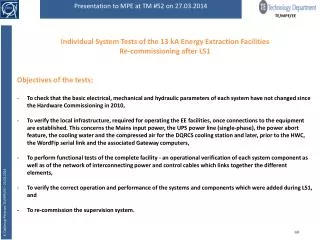
ELQA Campaigns for SMACC TE/MPE/EE LHC Machine • The AIV test (contd.) AIV test procedure generally requires electrical access to 4 Interconnects around the removed and replaced ‘N’-line (in yellow) of the half-cell in which a cryo magnet is being replaced. The cryo magnet replacement precedes the busbar consolidation by the ‘train’ K. Dahlerup-Petersen TE/MPE/EE – 5 November 2012
ELQA Campaigns for SMACC TE/MPE/EE LHC Machine Resources: Equipment & Manpower - for all ELQA LS1-related activities. PAQ: One TP4 system is required per PAQ test. 8 TP4 systems (+ 2 Spares) are available. We foresee up to 2 simultaneous PAQ campaigns, each requiring a team of 3 specialists. Typical duration of one PAQ campaign: 90 minutes (once the equipment is in place) One further team is kept as reserve. AIV: One AIV test system is required for a magnet replacement. 2 AIV testers are available. For each campaign a specialized team of 3 people is required. A second team is kept as back-up. The test duration is 2 hours (once the tester is in place). K. Dahlerup-Petersen TE/MPE/EE – 5 November 2012
ELQA Campaigns for SMACC TE/MPE/EE LHC Machine Human Resources related to the ELQA Test Campaigns: 4 collaboration agreements have been defined and signed, all with the institute HNINP, Cracow 1. KE1818/TE/LHC: Upgrade of two AVI systems andmanufacture and assembly of mechanical, electrical and electronic systems for constitution of 10 TP4 test systems, including software upgrades and upgrade of existing TP1, TP2, TP3 benches to be TP4 compatible. 2. KE2058/TE/LHC: 5 work-packages related to execution of standard ELQA measurements during LS1 (TP4E, TP4 A & B, TP4 C, MIC-W, MIC-C, DOC-W, DOC-C). 3. KE2059/TE/LHC: 9 work-packages for AIV and PAQ as well as consolidation of proximity equipment. 4. KE2060/TE/LHC: 4 work-packages for treatment of non-conformities, data handling during the ELQA campaigns, ELQA-related software maintenance and upgrades as well as HNINP team coordination. This in addition to the CERN ELQA ‘core’ team of nine people: four staff, one fellow, two PJAS, one TS and one FSU. K. Dahlerup-Petersen TE/MPE/EE – 5 November 2012
ELQA Campaigns for SMACC TE/MPE/EE LHC Machine Resource planning for ELQA-LS1 activities K. Dahlerup-Petersen TE/MPE/EE – 5 November 2012 Total envelope: 516 man-months (43 man-years). Jan 2013 – Dec. 2014. Team leaders, Engineers & Technicians.
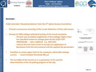
New HV Test Specification TE/MPE/EE LHC Machine Revision of HVQ Test Voltages: Reasons for revision of voltage withstand figures used during HV Qualification in the LHC: - Reference data for cold tests are still originating from the original document of Felix Rodriguez Mateos from Oct. 1998, revised once (Nov. 2004). - In this reference document each circuit is considered alone. For the busbar insulation of adjacent and nested circuits there’s a wish to consider the highest differential voltages. - The after-LS1 discharge time-constant of the Main Quad. Circuits has been fixed to 15 s (17.9 mΩ/19.0 mΩ) (if no quench-back) whereas τof the Main Dipole Circuits will go back to the original figure 105 s (2 x 70 mΩ) (from today’s 52 s - 2 x 140 mΩ). - Because of the particular topology of the Main Dipole Circuit the present test level does not cover the case of an earth fault. For all other circuits operational figures will be used with 20 % safety margin. - For the 3 Main Circuits voltage figures shall be related to nominal current, all other circuits to ultimate current. - Introduction of earth fuse supervision in the 6’000 DQHDS quench heater power supplies. K. Dahlerup-Petersen TE/MPE/EE – 5 November 2012
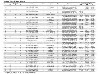
ELQA Campaigns for SMACC TE/MPE/EE LHC Machine • Some additional comments: • RB/RQF/RQD: Rated currents (7 TeV): 11850A /11162A/10677A rounded to 12000A/11200A/11200A • Vquench is obtained from quench calculations. For the main quadrupoles we assume that quenches in magnet coils do not propagate to the busbars. • The present test voltage for RB (1900 V) was calculated from operational scenario with 20% overshoot of extraction voltage. With capacitive snubbers the overshoot is eliminated. From worst-case considerations the RB test voltage shall be 2100 V. • New Quadrupole test voltage is 500 V (with 20% safety margin). BUT nearness of spools will require busbars tested to much higher value (= 1.2 x (VEEQuad + VEESpool) = 800 V). • For the spools we consider worst-case neighborship, i.e. spool-to-spool, giving 1000 V test voltage. • For nested magnets without EE: Worst-case consideration will give 2 x VQuenchplus20 % safety margin. • For the MIC-test of Quench Heater –to- coil (grounded) the test voltage can be reduced to • 1.2 (Vquench + 450 V) -see next table. K. Dahlerup-Petersen TE/MPE/EE – 5 November 2012
New H.V. Test Specification. TE/MPE/EE LHC Machine Proposed new test voltages: K. Dahlerup-Petersen TE/MPE/EE – 5 November 2012
ELQA Campaigns for SMACC TE/MPE/EE LHC Machine Suggested new test voltages for HVQ in all cryo magnets with heaters. All lower than equal the present test levels. K. Dahlerup-Petersen TE/MPE/EE – 5 November 2012 Consequences of the higher test voltages for coils and busbars: - It may be necessary to disconnect temporarily certain monitors such as the cryo sensors (insufficient rating of connectors). - The existing HV test generators of ELQA are limited to 2 kV. Replacement needed. - It is vital to perform tests with these higher levels before LS1 so to identify weak points (the individual magnets have been tested to higher voltages in SM18). - Breakdowns may cause voltage waves which could damage other equipment.
ELQA Campaigns for SMACC TE/MPE/EE LHC Machine • Conclusion: • All required test procedures are now available. The LS1 adaptation of the PAQ procedure is in circulation for approval. All test procedures will be registered as EDMS documents. • 10 TP4 systems are at the point of being ready, with new Labview software loaded, one station has been successfully tested in SM18 on s.c. load (Q5). • The TP4 systems are being equipped with new H.V. test generators and UPS’s. • Three contracts have been signed with the Polish Institute HNINP for supply of engineers, team leaders and technicians for the various LS1-realted ELQA jobs. • The MPE/EE/ELQA team will now begin an ‘internal’ training campaign for becoming familiar with the new TP4 system. • In parallel, the teams at NHINP, which are selected for the LS1 tasks at CERN, will undertake similar training using the two TP4 stations which are still in Cracow. The AIV teams will also repeat training. • The majority of selected people for the three contracts are ‘veterans’, many of them having experienced several ELQA campaigns at the LHC. • The new, higher test voltages will prevent operational breakdowns under worst-case conditions, in particular for adjacent busbars and nested magnet coils as well as for the main quadrupole circuits where extraction voltages will exceed 200 Vpeak(new arc chambers to be installed on the extraction switches during LS1). • It is important to test the LHC circuits at these higher test voltages at cold before LS1 so to identify at an early stage any weak elements. K. Dahlerup-Petersen TE/MPE/EE – 5 November 2012
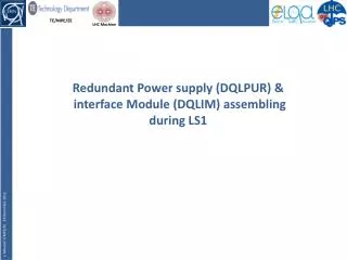
DQQDE Voltage-to-Ground Monitor. TE/MPE/EE LHC Machine DQQDE board for voltage-to-ground measurement Communication part Memory Analogue part with voltage divider ADUC controller DC-DC supply for +/- 15V and 5V K. Dahlerup-Petersen TE/MPE/EE – 5 November 2012 • The system wasdesigned for low-precision voltage measurements with the purpose of -Verifying the correct behavior of the Energy Extraction systems in the 3 Main Circuits • after each discharge – through a series of voltage plots as above. • -Facilitating the identification of the location of an earth fault with voltage breakdown. • -The system is a part of the nQPS systems installed under the MDB dipoles, i.e. in 54(55) locations per sector, 1308 monitoring boards in total. • -All nQPS crates were prepared for installation of the 3 DQQDE boards. A pre-series of 250 boards are now available but not yet installed. • -ACQ software was developed. • -It is the intention to install completely the system during LS1.
DQQDE Voltage-to-Ground Monitor. TE/MPE/EE LHC Machine • The question was: • Could this network of ground monitors be used for early detection of precursors for voltage breakdowns? • The facts: • As the system does not measure leakage currents, detection must be based on voltage variations. • With its present ADC the resolution is 61 mV. However, if replaced by a 24-bit versionthe resolution can be reduced to 0.2 mV. • Because of its high leakage current the ground connection of each board is opened during ELQA HVQ (test mode). The leakage currents during energy extraction (in normal operational mode) attains typically 0.1 – 0.5 mA . • The difficulties: • -During its normal operations mode the ground voltages varies from 0 to full extraction voltage depending on the place of the magnet in the chain. Only a few magnets experience the full extraction voltage (Rdump x Ipeak). • -If a dielectric breakdown is preceded by a rise in leakage current this can today only be detected at the grounding system of the power converter. • -Dielectric breakdowns are strongly non-linear phenomena (avalanche). The DQQDE system is slow: 5 Hz sampling frequency. • - The capacitive earth currents will complicate the precursor detection during voltage ramps. • BUT: • - PSpice simulations are ongoing in the MPE –Performance section to determine the voltage fluctuations in case of local degradation of the insulation resistance. K. Dahlerup-Petersen TE/MPE/EE – 5 November 2012
DQQDE Voltage-to-Ground Monitor. TE/MPE/EE LHC Machine Proposal: – if simulations suggest a measurable voltage modification: To equip the boards with 24-bit ADC’s and operate them in ‘normal mode’ in combination with ELQA HVQ . Test both ramped mode and steady-state voltage application. K. Dahlerup-Petersen TE/MPE/EE – 5 November 2012