Download
1 / 1
10 likes | 198 Views
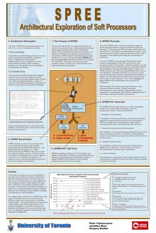
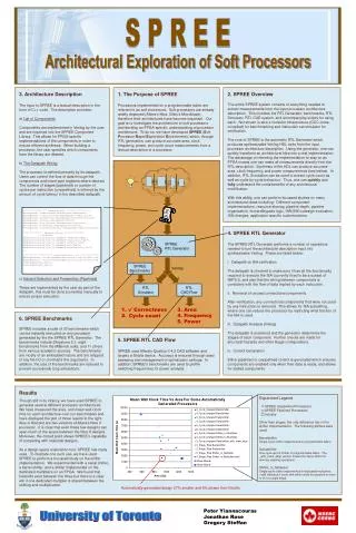
SPREE RTL Generator. SPREE Benchmarks. Verilog. RTL Simulator. RTL CAD Flow. . 1. 2. Correctness. Cycle count. 3. Area 4. Frequency 5. Power. Expanded Legend SPREE Unpipelined Processors SPREE Pipelined Processors Industry

E N D
SPREE RTL Generator SPREE Benchmarks Verilog RTL Simulator RTL CAD Flow 1. 2. Correctness Cycle count 3. Area 4. Frequency 5. Power Expanded Legend SPREE Unpipelined Processors SPREE Pipelined Processors Industry Other than stages, the only difference lies in the shifter implementation. The following shifters were used: Barrelshifter Single-cycle shifter implemented in programmable fabric. Serialshifter One cycle per bit shifter in programmable fabric. The _with_mem_align version shares the same shifter for memory aligning operations. Shifter_in_Multiplier Single-cycle shifter implemented in dedicated multipliers, +stall indicates 2-cycle shift which stalls the pipeline in order to fit in a single stage. S P R E E Architectural Exploration of Soft Processors 3. Architecture Description The input to SPREE is a textual description in the form of C++ code. The description provides: a) List of Components Components are implemented in Verilog by the user and are imported into the SPREE Component Library. This allows for FPGA-specific implementations of the components in order to ensure efficient synthesis. When building a processor, the user specifies which components from the library are desired. b) The Datapath Wiring The processor is defined primarily by its datapath. Users can control the flow of data through the components and insert pipe registers where desired. The number of stages (pipelined) or number of cycles per instruction (unpipelined) is inferred by the amount of cycle latency in the described datapath. c) Hazard Detection and Forwarding (Pipelined) These are implemented by the user as part of the datapath, this must be done (currently) manually to ensure proper execution. 1. The Purpose of SPREE Processors implemented on a programmable fabric are referred to as soft processors. Soft processors are already widely deployed (Altera’s Nios, Xilinx’s Microblaze), therefore their architectures have become important. Our goal is to investigate the architecture of soft processors and develop an FPGA-specific understanding of processor architecture. To do so, we have developed SPREE (Soft Processor Rapid Exploration Environment), which, through RTL generation, can produce accurate area, clock frequency, power, and cycle count measurements from a textual description of a processor. 2. SPREE Overview The entire SPREE system consists of everything needed to extract measurements from the input processor architecture description. This includes the RTL Generator, benchmarks, RTL Simulator, RTL CAD system, and accompanying scripts for using each. Not shown is also a compiler infrastructure (GCC cross-compiled) for benchmarking and instruction set simulator for verification. The core of SPREE is the automatic RTL Generator which produces synthesizable Verilog HDL code from the input processor architecture description. Using the generator, one can quickly transform an architectural idea into a real implementation. The advantage of intending the implementation to stay on an FPGA means one can make all measurements directly from the RTL description. Synthesis of the HDL can produce accurate area, clock frequency, and power measurements (see below). In addition, RTL Simulation can be used to extract cycle count as well as cycle-by-cycle behaviour. Thus, one can quickly and fully understand the costs/benefits of any architectural modification. With this ability, one can perform focussed studies on many architectural ideas including: Different component implementations, resource sharing, pipeline depth, pipeline organization, forward/bypass logic, HW/SW codesign evaluation, ISA changes, application specific customizations. /****************** Component List *******************/ RTLComponent *addersub=new RTLComponent("addersub"); RTLComponent *logic_unit=new RTLComponent("logic_unit"); RTLComponent *shifter=new RTLComponent("shifter","barrel"); RTLComponent *mul=new RTLComponent("mul"); RTLComponent *reg_file=new RTLComponent("reg_file"); RTLComponent *ifetch=new RTLComponent("ifetch"); RTLComponent *branchresolve=new RTLComponent("branchresolve"); /*************** Datapath Wiring ****************/ // RS Fanout addConnection(reg_file,"a_readdata",addersub,"opA"); addConnection(reg_file,"a_readdata",logic_unit,"opA"); addConnection(reg_file,"a_readdata",shifter,"sa"); addConnection(reg_file,"a_readdata",mul,"opA"); addConnection(reg_file,"a_readdata",branchresolve,"rs"); ... /*********************** Hazard detection *******************/ HazardDetector *rs_haz=newHazardDetector(rs_reg,"q",dst1,"q"); HazardDetector *rt_haz=newHazardDetector(rt_reg,"q",dst1,"q"); stallOnHazard(rs_haz,1); stallOnHazard(rt_haz,1); 4. SPREE RTL Generator The SPREE RTL Generator performs a number of operations needed to turn the architecture description input into synthesizable Verilog. These are listed below: i. Datapath vs ISA verification The datapath is checked to make sure it has all the functionality required to execute the ISA (currently fixed to be a subset of MIPS I), and also that the wiring between components is consistent with the flow of data implied by each instruction. ii. Removal of unused connections/components After verification, any connections/components that were not used by any instruction is removed. This allows for ISA subsetting, where one can reduce the processor by restricting what fraction of the ISA is used. iii. Datapath Analysis (timing) The datapath is examined and the generator determines the stages of each component. Further checks are made for structural hazards and other illegal configurations. iv. Control Generation Either pipelined or unpipelined control is generated which ensures components are enabled only when their data is ready, and allows for stalled components. 6. SPREE Benchmarks SPREE includes a suite of 20 benchmarks which can be instantly executed on any processor generated by the the SPREE RTL Generator. The benchmarks include Dhrystone 2.1, eight benchmarks from the MiBench suite, and 11 others from various academic sources. The benchmarks are mostly of an embedded nature and are stripped of any file I/O or command line arguments. In addition, the size of the benchmarks are reduced to prevent excessively long simulations. 5. SPREE RTL CAD Flow SPREE uses Altera’s Quartus II 4.2 CAD software and targets a Stratix device. Accuracy is ensured through seed sweeping and management of optimization settings. In addition, SPREE’s benchmarks are used to profile switching frequencies for power analysis. Results Though still in its infancy, we have used SPREE to generate several different processor architectures. We have measured the area, and mean wall clock time for each architecture over our benchmarks and have displayed the plot of those results to the right. Also in that plot are two versions of Altera’s Nios II processor. It is clear that even these few designs can span much of the space between the Nios II designs. Moreover, the circled point shows SPREE’s capability of competing with industrial designs. As a design space exploration tool, SPREE has many uses. To illustrate one such use, we have used SPREE to perform a focussed study on the shifter implementation. We experimented with a serial shifter, a barrel shifter, and a shifter implemented on the dedicated multipliers on an FPGA. We found that tradeoffs exist between the three but there is a clear win if one dedicated multipler is shared between the shifting and multiplication. Automatically generated design 27% smaller and 6% slower then NiosIIs Peter Yiannacouras Jonathan Rose Gregory Steffan University of Toronto