Download
1 / 1
10 likes | 158 Views
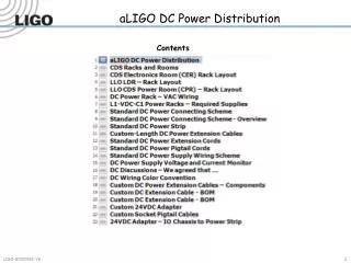
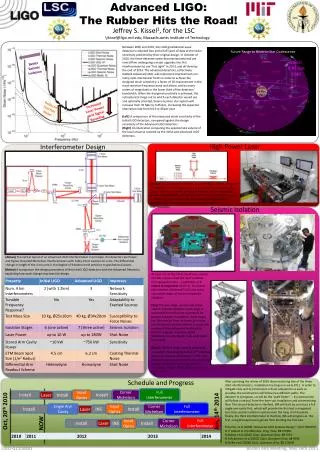
Advanced LIGO: The Rubber Hits the Road!. Future Range to Neutron Star Coalescence. aLIGO 0.45 Gpc 2014. Jeffrey S. Kissel 1 , for the LSC. iLIGO 35 Mpc 2007. 1 jkissel@ligo.mit.edu, Massachusetts Institute of Technology.

E N D
Advanced LIGO: The Rubber Hits the Road! Future Range to Neutron Star Coalescence aLIGO 0.45 Gpc 2014 Jeffrey S. Kissel1, for the LSC iLIGO 35 Mpc 2007 1jkissel@ligo.mit.edu,Massachusetts Institute of Technology Between 2005 and 2010, the LIGO gravitational wave detectorrs collected two and a half years of data at the strain sensitivity predicted by their original design. In October of 2010, the three detectors were decommissioned and are now offline undergoing a major upgrade; the first interferometer to see “first light” in 2013, and all three by the end of 2014. The advanced detectors, collectively dubbed Advanced LIGO, will implement improvements on many opto-mechanical fronts in order to achieve the designed strain sensitivity; a factor of 10 improvement in the most sensitive frequency band and above, and by many orders of magnitude in the lower third of the detectors’ bandwidth. When the designed sensitivity is achieved, the astrophysical range out to which each detector would see and optimally oriented, binary neutron star system will increase from 35 Mpc to 0.45 Gpc, increasing the expected obervation rate from 0.02 to 40 per year. Better Seismic Isolation Reduced Thermal Noise Increased Laser Power and Signal Recycling (Left) A comparison of the measured strain sensitivity of the Initial LIGO detectors, compared against the design sensitivity of the Advanced LIGO detectors. (Right) An illustration comparing the approximate volume of the local universe covered by the initial and advanced LIGO detectors. High Power Laser Interferometer Design (Above) The Advanced LIGO laser is a multi-stage, 180 W, 1064 nm wavelength laser. The light source is a 2W, Nd:Yag solid-state laser. This is fed into a medium power pump stage that increases the power to 35W. Finally, the light passes through a high-power ring oscillator stage to increase the output light to the full 180W. (Left) A picture of the fully-installed laser in the first interferometer. Seismic Isolation (Above) The optical layout of an Advanced LIGO Interferometer. In principle, the detectors are Power- and Signal- Recycled Michelson Interferometers with Fabry-Perot Cavities for arms. The differential change in length of the 4 km arms is the degree of freedom most sensitive to gravitational waves. (Below) A comparison the design parameters of the initial LIGO detectors with the Advanced Detectors, explaining how each change improves the design. At each end of the Fabry-Perot arm cavities, the test masses need the most isolation from ground motion – a reduction in 9 orders of magnitude at 10 Hz. To achieve this isolation, Advanced LIGO uses many successive stages of active and passive isolation. (Top) The two-stage, passive and active seismic isolation platform. Each stage is suspended from the next as pendula for passive isolation. In addition, these stages use information from on-board low-noise inertial sensors (seismometers) to sense the motion of the platform to feed-back to electro-magnetic actuators. (Left) SolidWorks model, (Right) Fully assembled first article. (Right) The four-stage, passive quadruple pendulum. Each stage provides 1/f2isolation above its resoance frequency (~ 1 Hz). The final two stages are monolithic fused silica to further reduce thermal noise. (Left) SolidWorks Model, (Right) Fully assembled first article Schedule and Progress After spending the winter of 2010 decomissioning two of the three LIGO interferometers, installation has begun in early 2011. In order to mitigate risks and to commission critical subsystems as early as possible, the construction will follow two different paths. The detector in Livingston, LA will be the “path finder” -- its construction will follow a natural, from-the-laser-out installation and commissioing flow. The second detector in Hanford, WA will start by construct a full single arm cavity first, which will provide the first test a integrated test-mass seismic isolation systems over the long, 4 km baseline. Finally, the third interferometer in Hanford, WA will progress as the first, using the experience gained from building the first two. Full Interferometer Corner Michelson Input Optics Install Install Laser Install Full Interferometer Single Arm Cavity Input Optics Corner Michelson Install INS Install Laser Oct, 20th 2010 Jun, 14th 2014 Full Interferometer Input Optics Corner Michelson NOW Boston AAS Meeting, May 26th 2011 Install Laser INS Install Fritschel, et al(2009) “Advanced LIGO Systems Design.” LIGO T010075. B. P. Abbott et al (2009) Rep. Prog. Phys.72 076901 R Abbott et al (2002) Class. Quantum Grav.19 1591 N A Robertson et al (2002) Class. Quantum Grav.19 4043 B Willke et al (2008) Class. Quantum Grav.25 114040