Download
1 / 44
440 likes | 560 Views
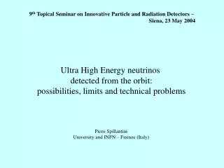
9 th Topical Seminar on Innovative Particle and Radiation Detectors – Siena, 23 May 2004. Ultra High Energy neutrinos detected from the orbit: possibilities, limits and technical problems. Piero Spillantini University and INFN – Firenze (Italy). Ultra-High Energy CR [AUGER, TUS, EUSO,

E N D
9th Topical Seminar on Innovative Particle and Radiation Detectors – Siena, 23 May 2004 Ultra High Energy neutrinos detected from the orbit: possibilities, limits and technical problems Piero Spillantini University and INFN – Firenze (Italy)
Ultra-High Energy CR [AUGER, TUS, EUSO, KLYPVE?,OWL??] Indirect detection (EAS) [arrays & florescence] Direct detection Balloons & Satellites GeV | TeV | PeV | EeV | ZeV | CR flux – 5 boxes
Ultra High Energy cosmic rays Extragalactic (gyro-radius) Unknown acceleration mechanism: - cannot arrive from far away (CMB interaction) - no sources identified in 50-100 Mpc distance Possible UP-DOWN generation: - e.g. topological defect decay
1 pc = 3.3 ly = 3.1 1016 m Protons: Interaction with CMB (2.7 K) photons p + g D+(1232) pN Energy threshold: 5x10¹⁹ eV GZK (Greisen, Zatsepin, Kuzmin) cutoff Attenuation length 100 Mpc a) Nuclei: Fotodisintegration by CMB (2.7 K) photons Attenuation length 10 Mpc Electrons and photons: Pair production on CMB Compton scattering attenuation length 10 Mpc Neutrons: b decay Range 1 Mpc (g 1011) b) Neutrinos: attenuation length 40 Gpc c) Attenuation length 100 Mpc what particles? from where? • Nucleons and nuclei? • Electrons and photons? • Neutrinos?
EAS Fluorescence from space Comparison of the EECR Experiments Experiment situation ‘effective’ area size (km2sr) Fly’s Eye completed 400 AGASA running 200 HiRes running 500 Auger/array under construction 7000 “ (Hybrid) “ “ 700 TUS in preparation* 6,000 KLYPVE project 20,000 EUSO approved phase A* 50,000 OWL proposed 300,000
The EUSO optics design consisting of two 2.5 m diameter plastic Fresnel lenses which focus light on a curved focal surface (right). Pupil
EUSO OWL ??? (two satellites) Russian sector ESA module Japanese modules (Argentina site) TUS (on Satellite) KLYPVE ?? AUGER on ground
Basic EUSO Instrument Observational characteristics for the EECR/n telescope are: Field of View± 30° around Nadir Lens Diameter 2.5 m Entrance Pupil Diameter ³ 2.0 m F/#< 1.25 Operating wavelengths300-400 nm Angular resolution (for event direction of arrival)~ 1° Pixel diameter (and spot size)~ 5 mm Pixel size on ground~ 0.8 ´ 0.8 km2 Number of pixel~ 2.5 ´ 105 Track time sampling (Gate Time Unit)833 ns (programmable) Operational Lifetime3 years
Multi-OWL Detector 1000 km 6680km R=6380km Earth 30o 30o 3340km Side View Top View
Cosmogenic neutrino component Protons coming from distances >20-50 Mpc interact with the CMB (GKZ effect) producing pions, and finally neutrinos (3 at each interaction). Protons with E>1020eV interact several times before degrading under the GKZ cut-off producing many e andneutrinos. The energy of produced neutrinos is more than 1018eV
This is the “less unprobable” neutrino component expected at the extreme energies. It is not “model dependent” (i.e. it only depends from the proton source distribution) No other neutrino sources will be considered, even if potentially much more abundant (such “Top-Down” processes and models connected with GRB’s)
EUSO min Max
The last more complete work is “Ultra-High Energy Neutrino Fluxes and Their Constraints” (Kalashek, Kuzmin, Semokov, Sigl) [arXiv:hep-ph/0205050 v3 13 Dec 2002]
How increase the number of neutrino events? x 1.5 x 9 (x 30) (x 20) x 3 • Decrease the energy threshold (5 x 10¹⁹eV 1018eV) • by improving the sensor efficiency (0.20 0.50) • by improving the light collection (pupil 2m 6m) • (what implies reflective systems and modularity) • Increase the target volume • by increasing the FOV (60° 140.8°) • (limited to 130º by attenuation by air and by distance)……. • (light attenuation 0.5 for FOV 90°) ……………….
6 2 Area of the calotta (10 Km) 15 90 80 70 Area of the calotta Area seen by EUSO 60 10 50 40 5 30 20 10 100 attenuation due 10 to geometry attenuation due * to atmosphere TOTAL attenuation Attenuation factor 0.5 (EUSO) 0 distance from Nadir (Km) 1000 1500 2000 500 1/2 FoV 30° 70° 60° 65° 45° * Considered from the sea level HORIZON
p + g D+(1232) pN e EUSO EUSO x 30 Max ~min
Euso x 2.5 F=5 Euso x 2.5 F=10 Euso x 2.5 F=2 Euso F=2 Max min
golden Fluorescence only Xmax Select. Shape Select. Rejection > 10-4
EUSO like Multi-mirror • H (km) 400 400 • Total FoV (o) 60 90 • Radius on ground (km) 235 413 • Area on ground (103km2) 173 536 • Pixel on ground (km * km) 0.8 x 0.8 1.6 x 1.6 • pixel on detector (cm) 0.6 2.0 “ “ with corrector 1.2 Area/pixel (n. of pixels) 270k 238k Pupil diameter (m) 2.0 2.0 5.0 7.5 10.0 Photo detection efficiency 20% 50% 50% 50% 50% E threshold (EeV) 50 20 5.5 3.2 2.3 Proton events/year, GKZ + uniform source distrib. 1200 8000 300k 900k 1800k with Ep >100 EeV) 100 100 310 310 310 Neutrino events per year ( min)0.6 1.5 18 30 42 Neutrino events per year ( Max) 12 18 108 120 138
2 5 10 m 20 5 2.2 EeV (Threshold for: h=400km and light detection efficiency 50%)
trigger data handling telemetry deployment single mirror field of view sensors total field of view d
A proposed 5 m EPD mirror system INOA Design of a mirror optics, based on the Schmidt camera principle, with FOV up to 25° Design of a mirror optics, based on the Schmidt camera principle, with FOV up to 25° light shield mirror correcting plate and/or filter light shield mirror correcting plate and/or filter FEATURES FEATURES • Entrance pupil MUST be in the mirror centre of curvature • Mirror is then larger than EPD (depending on FOV) • Light shield is anyway necessary for stray light reduction • The correcting plate greatly improves performances • F/# investigated as low as 0.6 • Detector diameter smaller than any other proposed solution • Weight saving solution (both for optics and detector) • Obscuration acceptable for FOV up to 25° • Vignetting almost constant for all FOV • Low sensitivity to misalignment (except decenter) • Optical system design scalable to any dimension focal plane focal plane
Resolution of 5 m EDP reflecting system INOA Spherical mirror with ± 25° FOV Spherical mirror with ± 15° FOV Spherical mirror + Schmidt corrector Spherical mirror + Schmidt corrector optimized at marginal field angles Aspherical mirror + Schmidt corrector
In orbit mirror deployment INOA The proposed mirror diameter requires in orbit deployment or assembling Maximum diameter possible with current launchers is 3m Angular tollerance are not so stringent, 0.1º (0.001º mechanically possible) • Possible deployment techniques • Self deployment (like most antennas) • Assembling by robots on the Shuttle • Assembling by robotic arms on the ISS • After assembling on ISS, the system could remain as external payload, as EUSO • OR • Several systems could be assembled this way then moved to a different orbit as free flyers • (space factory concept)
Conclusions INOA • A mirror system is a consistent solution for post-EUSO • The construction is possible with existing technologies • The system can be scaled up, to get: • higher signal lower threshold energy • higher orbit increased observed area • Some further optimization is possible • Many items still to be investigated: • tolerances • thermal behavior • supporting mechanics • detectors • costs...
Schematic example of the EUSO focal surface assembly showing how the individual macrocells could be mounted to approximate the curve focal surface of the optics. The shape of the focal surface shown in the figure does not correspond to the “real geometry” but it is meant to give an overall artistic vision of the assembly philosophy. Eachmacrocell consists of 6x6 Photomuliplier Tube assemblies, associated light guides and electronics and is a modular unit. Fig. 3.5 - Each PMT is a commercially available 8x8 anode device; here it is shown with a possible light guide used to match the active area to the focal surface.
Configuration 3 with the Main Telescope (MT) and the Auxiliary Telescopes (AT).
Euso x 2.5 F=4 Euso x 2.5 F=10 Euso x 2.5 F=6 Euso x 2.5 F=2 Euso F=2 Max min
Euso x 2.5 F=4 Euso x 2.5 F=10 Euso x 2.5 F=6 Euso x 2.5 F=2 Euso F=2 min Max min
Euso x 2.5 F=4 Euso x 2.5 F=10 Euso x 2.5 F=6 Euso x 2.5 F=2 Euso F=2 Max min
Euso x 2.5 F=5 Euso x 2.5 F=10 Euso x 2.5 F=2 Euso F=2 min Max
EUSO like Multi-mirror • H (km) 400 400 • Total FoV (o) 60 90 • Radius on ground (km) 235 413 • Area on ground (103km2) 173 536 • Pixel on ground (km * km) 0.8 x 0.8 1.6 x 1.6 • pixel on detector (cm) 0.6 2.0 “ “ with corrector 1.2 Area/pixel (n. of pixels) 270k 238k Pupil diameter (m) 2.0 2.0 4.0 6.0 10.0 Photo detection efficiency 20% 50% 50% 50% 50% E threshold (EeV) 50 20 5 2.2 0.8 Proton events/year, GKZ + uniform source distrib. 1200 8000 270k 1800k 15000k with Ep >100 EeV) 100 100 310 310 310 Neutrino events per year ( min)0.2 0.5 7 14 31 Neutrino events per year ( Max) 4 6 37 46 56
Obscuration of the focal plane FOV 40° FOV 50° FOV 60°
F/# Vignetting of a lens system Still the Leica Noctilux-M 50 F / 1.0 Transmission of wide field, low F/#, lens systems is low at edge field signal at marginal field angles may be under threshold !