Download
1 / 17
170 likes | 238 Views
Transient Tolerant Surface Development. C.P.C. Wong 1 , D. Rudakov 2 , B Chen 1 , Hassanein 3 , A. McLean 4 and DIII-D support 1 General Atomics, P.O. Box 85608, San Diego, CA 2 UCSD, San Diego, CA 3 Purdue University, West Lafayette, IN 4 PPPL, Princeton, NJ. PFC annual meeting

E N D
Transient Tolerant Surface Development C.P.C. Wong1, D. Rudakov2, B Chen1, • Hassanein3 , A. McLean4 and DIII-D support1General Atomics, P.O. Box 85608, San Diego, CA2UCSD, San Diego, CA 3Purdue University, West Lafayette, IN 4 PPPL, Princeton, NJ PFC annual meeting UCLA August 4th 2010
Surface Material is a Key item for Fusion Development Surface material is critically important to next generation tokamak devices: • Plasma performance is affected by transport of impurities • Surface heat removal, tritium co-deposition and inventory will have impacts on material selection for devices beyond ITER • Radiation effects from neutrons and edge alphas, material design limits and component lifetimes will have to be taken into consideration DIII-D C-Mod AUG JET-ILW EAST ITER NFSF DEMO Be/W/C C/W Be/W/C ? ? W Mo C (High neutron and edge alpha fluence) Surface material options C and Be will not be suitable for the next generation devices and DEMO due to surface erosion and radiation damage. Presently W is the preferred choice, but feasibility issues have been identified
Significant Issues Projected for W-surface Operation ITER disruption loading: 10-30 MJ/m2 for 0.1 to 3 ms When exposed to He at high temperature, W surface showed growth of W nano-structure from the bottom; the thickness increases with plasma exposure time Baldwin and Doerner, Nuclear Fusion 48 (2008) 1-5 Irreversible surface material damage M. Rödig, Int. HHFC workshop, UCSD Dec. 2009 We cannot eliminate un-predicted disruptions even if disruption detection and mitigation work perfectly
Damages to W First Wall have also been Projected Low energy He+ irradiation in plasma simulator NAGDISH bubble and hole formation on W surface @ > 10 eV D. Nishijima, Journal of Nuclear Materials, 329 (2007) 1029-1033
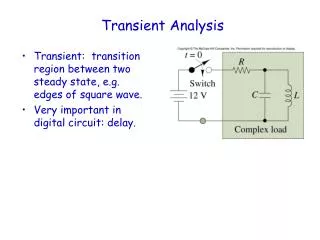
How about Li-wall? A Very Optimistic Estimate of First Wall Heat Removal Shows the Heat Flux Limit of Li Surface • Assumptions: • Structural material – Ferritic steel, kth@20 W/m.k • Helium coolant @ 8 MPa • He Tin@ 340° C • Coolant velocity @ 100 m/s • Square channel geometry, width = 2 cm • Wall thickness = 4 mm • Channel length = 1 m • Film drop enhancement = 1.8 via twisted tape • Li thickness = 0.0 Li surface facing the plasma A ferritic steel first wall square He channel unit cell He coolant FS Tmax,C Temp, C • Limitations: • Ferritic steel Tmin> 350° C, • limited by radiation hardening • Li surface Tmax< 400° C , limited by vaporization into the plasma core FS Tmin,C Heat flux, MW/m2 T. Roeign et al, J. of Nucl Mat. 290-293 (2001) 312-316 • Result: • Li surface at the first wall is limited to < 0.2 MW/m2, due to the vaporization of Li unless • it is demonstrated experimentally that Li will have limited transport into the plasma core
Plasma Facing Material Design and Selection Requirements for Next Generation Devices • Withstand damage from DT generated He • Withstand transient events like ELMs and disruption • Additional critical requirements: • Physics performance: • 3. Material suitable for high performance plasma operation • 4. Suitable for edge radiation to reduce maximum heat flux at the divertor • 5. Acceptably low physical and chemical erosion rate • Engineering performance: • 6. Transmit high heat flux for high thermal efficiency conversion • 7. Minimum tritium inventory • 8. Minimum negative effect to tritium breeding performance • 9. Low activation materials • 10. Replenish damaged surface material suitable for steady state • operation and long lifetime • Match materials temperature design requirements • 12. Withstand high neutron fluence at high temperature
A Possible PFM Concept that could Satisfy all Requirements • The concept: Si-filled W-surface (3,4,9) • •Protect the W surface from He damage with • the presence of Si (1) • •Exposed W will have a low erosion rate (5) • •Transmit high heat flux, e.g. The W-disc can be about 2 mm • thick and with indents, thus retaining high effective kth of • W layer, necessary for DEMO (6,8,11) • Should provide enough Si to withstand ELMs and a few disruptions • (modeling showed vaporized Si ~10 μm/disruption including vapor • shielding effect) “W-Tmelt@ 3410°C, Si-Tmelt@1412°C, Si-Tboil@ 2480°C” (2) • •Should be able to control tritium inventory at temperature ~1000 °C (7) • •Suitable real time siliconization can be used to replenish Si when and where needed (10) • (Satisfying most requirements and unknown for #12 TBD) W-buttons W-buttons filled with Si
Si W surface progress • 2008: started with BW-mesh , but the presence of • C formed B4C, WB, W2B, W2B5, WC, and W2C, • thus broke up the mesh • 2009 changed from mash to plate, but B fill fell off • the holes • Switched to Si due to much better match in the • coeff. of thermal expansion between Si and W • High melting temperature of Si can form low • melting point W-Si chemicals • DIII-D boronization confirmed B coating thickness • of 0.75 μm < 1 μm coated • 2010: Drilled indents on W-button and the Si • was filled in powder form with binder and sintered • Si filled W buttons exposed in DIII-D W-mesh Damaged W-mesh W-disc B-coating W-buttons W-buttons with Si
Si-W Buttons and Sample before Exposure W-buttons with 1mm diameter and 1 mm deep indents W-buttons filled with Si From left to right: 2 Si-filled W-buttons 3 graphite buttons 2 W-buttons with indents W-buttons from UCSD Via K. Kumstadter DiMES button sample module front face 4.78 cm in diameter
Initial Results of Transient Tolerant Si-filled W-buttons Si filled W-buttons W-buttons with 1 mm dia. indents Loaded DiMES sample 2 Si-W, 3 graphite, 2 W buttons Shot 14261-14264 Shot 142706 Sample exposed To 4 LSN discharges Exposed in DIII-D lower divertor After one additional disruption shot without thermal dump on DiMES
Plasma shot # 142706, with relative stable plasma shape Langmuir probes Langmuir probe 23 Data on electron density, #/cm3 3005 ms ne Added neutron beam injected at 2000 ms, plasma ended with disruption ~ 3100 ms but migrated upward, no thermal dump on DiMES Time, ms 55 ms 105 ms 505 ms 1005 ms 2005 ms Plasma evolution DiMES
Discharge # 142706 Rad. Power Core Div NBI
Mostly CII/CIII emission measured during discharge and disruption (387, 392, 407 nm), additional CI (375 nm) in disruption Emission lines from the Atomic Line List
No significant Si lines measured except possibly at 385 nm (seen in the disruption only) Emission lines from the NIST database
Emission of W unlikely due to lack of strong 400.8 nm line emission (rel. int. 1000) Emission lines from the NIST database
Details show melted Si but minimum transport Mostly W, but Si and W lines are close Mainly C a little Si & O Tmelt: 1412 C Tboil: 2480 C, W Tmelt: 3380 C
Si-W Buttons Exposure Observations • As expected surface Si on the W button got removed during discharges easily at least from the first 4 shots, Si melting could have occurred during these shots • Favorable result shows much of the Si is retained in the indents even under additional exposure (142706) the radiation is mainly from carbon • Retained Si could demonstrate the vapor shielding effect to protect the W-button surface from melting under disruption thermal dump, which will need to be demonstrated • W-buttons were not damaged, observed cracks could be due to drilling of dents • Additional analysis to be performed on other 4 shots (no Ocean Optics was available) and look at the heat flux variation for the melting of Si • Disruption tolerance to be demonstrated along with variations in W-material, and optimization on indent geometry and Si-fill method • New samples will be fabricated and expose to thermal dump during disruption