Download
1 / 30
300 likes | 456 Views
An EBIS-based RHIC Preinjector - Test EBIS Results. Ed Beebe Preinjector Group Collider-Accelerator Department. Linac-based Preinjector - Source “requirements”. Intensity for 1.2 x 10 9 Au ions/bunch in RHIC : ~ 3.4 x 10 9 Au 32+ ions/pulse from the source

E N D
An EBIS-based RHIC Preinjector-Test EBIS Results Ed Beebe Preinjector Group Collider-Accelerator Department EBIS Project Technical Review 1/27/2005
Linac-based Preinjector - Source “requirements” • Intensity for 1.2 x 10⁹ Au ions/bunch in RHIC : ~ 3.4 x 10⁹ Au32+ • ions/pulse from the source • 2. No stripping before Booster injection : q/m > 0.16 (Au32+, Si14+, Fe21+) • 3. 1-4 turn injection into Booster : pulse width 10-40 s • (Note - 1 & 3 result in a Au32+ current of 1.7 - 0.42 mA) • 4. Rep rate : ~ 5 Hz • 5. Emittance : 0.2 mm mrad, normalized, rms • (for low loss at Booster injection) EBIS Project Technical Review 1/27/2005
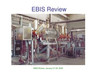
EBIS Test Stand (prototype) Test EBIS - 1/2 length prototype, but with the full power electron beam
Test EBIS - showing ion injection arm and extraction to Time-of-Flight Spectrometer Ion injection arm • Non-destructive current measure of injected and extracted beams can be made on current transformer. • Low resolution in-line TOF (between ion beam chopper and FC2) • High resolution TOF in energy focusing Mamyrin spectrometer
Some Principles for a Reliable, Low Maintenance EBIS The basic principle that has been followed is to separate the functions of source components and remove as much of the action as possible from the high vacuum ionization region. Provide beam current loss monitoring on all elements in beam path Avoid magnetic shims and shields where possible; allow for external corrections or reshaping of magnetic geometry External ion injection: EBIS acts as a charge state multiplier, low contamination, high reliability
Test EBIS performance represents more than an order of magnitude improvement over past EBIS sources. At the same time, operation has been very reproducible and stable. Some of the key features, almost all of which are unique to this EBIS, are the following: Design Choices for a Reliable, Low Maintenance EBIS 2 • A novel electron gun design from Novosibirsk. Convex LaB6 & IrCe cathodes • A warm bore, unshielded superconducting solenoid for the main trap region • Careful vacuum separation of the trap region from the electron gun and electron collector regions • Large bore (31mm) drift tubes have been used (pumping, reduced alignment precision, fast extraction, reduced RF coupling) • The use of auxiliary (warm) solenoids & many transverse magnet coils for steering corrections • The electron beam is pulsed to reduce the average power on the electron collector • Very versatile controls allow one to easily apply a time dependent potential distribution to the ion trap
E-Gun Chamber and Cathode Unit Electron Gun chamber with gate valve installed at Test EBIS Electron gun cathode unit with LaB6 cathode is shown above. EBIS Project Technical Review 1/27/2005
Electron Collector and Vacuum Housing View from ion extractor end (extractor not installed) EBIS Project Technical Review 1/27/2005
Drift Electrode Structure of the Test EBIS Ionization Region Drift electrode structure spans the length of the central vacuum chamber within theTest EBIS Superconducting Solenoid bore (above). Close-up of electrical leads (right). EBIS Project Technical Review 1/27/2005
External Sources used for Primary Ion Injection at the Test EBIS Hollow Cathode Ion Source (HCIS) Low Energy Vacuum Arc Source (LEVA) EBIS Project Technical Review 1/27/2005
IrCe Gun, Gate Valve, and Anode Modification • Cathode replacement and electron gun upgrades without disturbing ionization volume ultra-high vacuum. • Anode/Drift Tube geometry eliminates need for an additional auxiliary solenoid • Electron beams up to 10A, 100kW have been propagated with very low loss, usingIrCe Cathodes from BINP, Novosibirsk. • 10 A electron gun with IrCe cathode meets the RHIC EBIS requirements, with an estimated lifetime of >20,000 hours
Gold injection From Leva Top trace: Extracted current without ion injection Middle trace: Extracted current after Gold injection from LEVA source Bottom trace: integrated charge (13.3nC) extracted from EBIS 2ms after gold injection from LEVA
Results from Test EBIS ( ½ Length of RHIC EBIS) 5.5 x 10¹¹ charges/pulse are required for RHIC. By doubling the EBIS trap length to 1.5 m, we will exceed this requirement. (The ion yield has been shown to scale linearly with trap length). Time-of-flight spectrum peaked at Au 34+
Comparison of experimental and predicted ionization time of Au34+ Experiment: Au34+ produced in 50ms, with 7.2A, 20.5keV e-beam For Test EBIS, 10A e-beam j10A~575 A/cm2 Then J8A~0.72*575=414A/cm2 TTheory =( jT)Theory/J8A=0.048sec So the experimental production of Au34+ with a 50 ms confinement period is in good agreement with the 48ms predicted time. This means that the Au ions are confined well in the EBIS electron beam. Computer calculation of successive ionization of Au with a 20keV electron beam: 1.3 (jT)Theory=101.3=19.95
Extraction of ions from the EBIS trap The design goal of the Test EBIS is that 50% of the electron beam charge be neutralized by the ion species of interest (e.g. gold ions). Excellent ion yields from the trap, with very high beam neutralization efficiencies have been achieved 5.5 x 10¹¹ charges/pulse are required for RHIC, from a trap length of 1.5 m, and assuming operation at 10 A electron current. (The ion yield has been shown to scale linearly with trap length and electron current).
Au32+ Pulsed Ion Currents By manipulation of the EBIS trap electrodes (Fast extraction), the EBIS extracted charge can be delivered in pulse widths necessary to meet single to multi-turn injection requirements of the synchrotron. *(Typical extraction pulse widths without fast extraction)
Inline Time-of-Flight • Full ion beam sampled and collected on Faraday Cup • Ie= 7A; • 10 ms confinement • Au = 83%; C&O = 15%; H = 2%
Measured Emittance for a 1.7mA Gold Beam Emittance of a 1.7 mA extracted beam from EBIS, with Au injection. (n, rms)= 0.1 mm mrad. All charge states, peaked around Au25+. The emittance of light ions from EBIS is expected to be less due to less heating by the electron beam during relatively short confinement times necessary to reach charge states of interest.
Ion output vs Ion Trap Length Experimental conditions: Iel=7.5 A, Lshort=71 cm, Llong=107 cm, Btrap=4.6 T, Bmin=0.19 T Geometry of EBTS electro-optical system (top) and axial magnet field distribution with simulated radial profile of electron beam (bottom).
ab Charge state spectra of ions extracted from the long (a) and short (b) traps after confinement time 2.5 ms for = 7.5 A. Cursor for both cases is on Au19+. Time evolution of the total extracted ion charge (nC) with Au injection for the long trap (solid line) and short trap (dashed line). The capacity of ion trap is proportional to the length of the trap (as typically observed in any EBIS). The loss of ionization factor for a long trap, as observed in the spectra, is due to very low magnetic field on the peripheral parts of the long trap and will be avoided in the RHIC EBIS by maintaining the full field throughout the trap. The ion intensity is expected to double with the doubled trap length in the RHIC EBIS.
Hollow Cathode Ion Source at Test EBIS • Cu+1 >25mA, Ne >80mA • PEBIS~2x10⁻¹⁰ mb for PHCIS~1mb, 10ms, 1Hz shutter operation P~4x 10⁻⁸ mb P~4x 10⁻⁶ mb P~8x 10⁻⁵ mb P~0.8mB
Electronically Controlled Shutters Electronically controlled shutters are used to help provide differential pumping in the ion injection beam line. (25mm aperture, 6ms minimum open time)
EBIS Voltage and Timing Controller • The controller coordinates the application of all time dependent voltages and timing references associated with EBIS operation with a time resolution of 1 s, such as: • •Time dependent ion trap HV • • Electron beam ramping • •Table Driven Beamline Optics for Ion injection from Multiple sources and EBIS ion beam extraction
Multiple Ion Species (PPM) • The EBIS highly charged ion beam species and charge state can be selected on a pulse to pulse basis • Voltage Controller is hardware configured for 3 independent cycles with a repetition factor of up to 15 each • Software presently allows for use 16 independent beamline optics tables for selecting injection from various external sources or EBIS beam propagation to various diagnostic devices (RFQ, TOF, emittance analysis, etc).
Test of unregulated electron collector supply • In the normal Test EBIS setup, a highly regulated supply provides both electron collection and cathode biasing functions. • A test was performed to test the feasibility of using separate collector and cathode biasing (accelerator) supplies: • An unregulated, high current supply for • electron beam collection • A low current regulated supply to provide: • 1) stable e-beam launch • 2) Independent acceleration voltage • 3) Electron beam fault protection • Results using a 50mF Capacitor as a Collector Supply: • 4A electron beam, 50ms pulse: • droop ~3.7kV from nominal 10kV • good e-beam propagation • Lower Cost Unregulated Collector Supply • can be used in RHIC EBIS • (Ion Injection and extraction will be locked to repetitive waveform to minimize optical effects) Normal Test EBIS Configuration Experimental Test & Rhic EBIS Configuration
EBIS Results and Rhic design Parameters *Estimated result for data with 8A e-beam