More fun with Timer/Counters
More fun with Timer/Counters. Timer Input Capture. 4 main functions built around the Timer/Counter subsystem. Pulse accumulator (T/C connected to external clock) Allows counting of external events Output Compare Set a register flag when timer reaches a certain value

More fun with Timer/Counters
E N D
Presentation Transcript
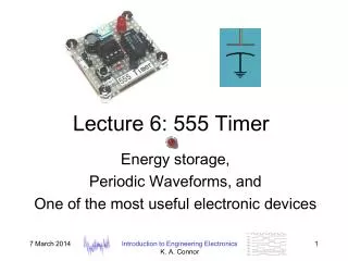
More fun with Timer/Counters Timer Input Capture CS-280 Dr. Mark L. Hornick
4 main functions built around the Timer/Counter subsystem • Pulse accumulator (T/C connected to external clock) • Allows counting of external events • Output Compare • Set a register flag when timer reaches a certain value • optionally cause an interrupt • Optionally set/clear/toggle output bits to generate variable freq. • PWM Generator • Periodic waveform generator of variable widths (duty cycle) • Input Capture • Set a flag when input bit rises/falls • optionally cause an interrupt • Can record the actual Timer/Counter value CS-280 Dr. Mark L. Hornick
Timer Input Capture (TIC) records the times of external Events Only possible with Timer/Counter 1 • the16-bit T/C “Events” are (externally-generated) signals on the Input Capture Pin (ICP) • PortD pin 6 (PD6) is the ICP • DDRD must configure PD6 for input CS-280 Dr. Mark L. Hornick
Current time of T/C1 is latched when an “Event” occurs • Timer/Counter1 ticks use two 8-bit TCNT1 registers to count timer increments • TCNT1H and TCNT1L • Event time is captured in two 8-bit ICR1 registers • ICR1H and ICR1L CS-280 Dr. Mark L. Hornick
Controlling Timer/Counter 1 • Like T/C0, the operation of T/C1 is controlled via various I/O registers • TICIE1 – T/C1 Input Capture interrupt enable bit • OCIE1A – T/C1 Output Compare A interrupt enable • OCIE1B – T/C1 Output Compare B interrupt enable • TOIE1 – T/C1 Overflow interrupt enable CS-280 Dr. Mark L. Hornick
T/C1 Flag Register • Like T/C0, the status of T/C1 overflow and output compare is readable via TIFR • ICF1 – Set on T/C1 input event • OCF1A – Set on Output Compare A match • OCF1B – Set on Output Compare B match • TOV1 – Set on Overflow CS-280 Dr. Mark L. Hornick
Details: Specifying the mode of operation of T/C1 for IC • Unlike T/C0, there are two Control Registers for T/C1 • TCCR1A is used when using T/C1 in Output Compare & Waveform Generation modes • Set all bits to 0 when only using Input Capture • WGMxx bits are used to set Normal/CTC/PWM modes CS-280 Dr. Mark L. Hornick
Controlling the Event that gets captured • ICNC1 – noise canceller • If 1, sampling is extended over 4 clock cycles • ICES1 – Input Capture Edge Select • Specifies which “Event” triggers Input Capture • 1: rising edge • 0: falling edge • WGM13:12 • leave 0 for Input Capture • CS12:CS10 control the counter frequency • Similar to settings for T/C0 CS-280 Dr. Mark L. Hornick
Servicing an Input Capture Interrupt • Example: Measuring the period T of a square wave: • Setup T/C1 for Input Capture • Enable Input Capture interrupt • Set T/C1 frequency • Set to trigger ICR1 interrupt on rising edge • Within Input Capture ISR • Read ICR1L and ICR1H • As with ADC, order is important • Save ICR1L and ICR1H • Reset ICR1 to trigger next time on falling edge • On second interrupt (falling edge) • Read ICR1L and ICR1H • Compute counter delta • Compute time period T from delta and frequency • Reset ICR1 to trigger on rising edge T CS-280 Dr. Mark L. Hornick
An Application Example • Incremental Encoder • Used to monitor the position of rotational devices (motors, machine shafts, etc) • Often known as quadrature encoders CS-280 Dr. Mark L. Hornick