Download
1 / 20
200 likes | 222 Views
Detailed design documents, shielding policy, and calculations for radiation protection in NSLS-II accelerator complex based on DOE regulations. Emphasizing safety and ALARA principles.

E N D
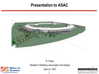
Presentation to ASAC R. Casey Radiation Shielding: Assumption and Design April 24, 2007
Preliminary Shielding Design Documents for NSLS II 1. Linac, NSLS II- TN 12 2. Booster & Storage Ring, NSLS II – TN 13 3. Storage Ring Supplemental Shielding – TN 21 4. Beamlines and Front Ends, NSLS II – TN 14 5. Ray Tracing Standards, NSLS II – TN 20 6. Activation Analysis, NSLS II – TN 15 & 16
Radiation Safety Workshop was Recently Conducted • March 27 – 28, 2007 • Membership • S. Rokni (Chair) – SLAC • R. Donahue – ALS • P. Berkvens – ESRF • D. Beavis – BNL • C. Schaefer - BNL
Rad Safety Workshop • Committee reviewed: • Shielding methodology & assumptions • Interlocks, Critical Devices, and Area Radiation Monitoring plans. • Committee concluded: “Given the status of the project, the design of the bulk shielding of the accelerator complex is well developed and is based on sound principles and reasonable assumptions. “
Desired Shielding Outcome • Compliance with DOE Orders, Part 835, and BNL Administrative Controls • < 25 mRem/year (.25 mSv) on-site to non-NSLS-II personnel; < 5 mrem/year (0.05 mSv) at site boundary • Radiation exposure to users and staff ALARA – an administrative control level of 100 mRem/year (1 mSv) is desired • We plan to achieve this through shielding and engineering controls; & supplemental administrative controls • Based on current experience, we expect annual radiation exposures < < 100 mRem/year (1 mSv) to NSLS staff and users • After verification, we expect short-term visitors will not be required to have dosimeters routinely
Shielding Policy • Accelerator and beam line enclosures will be shielded to reduce exposure at the exterior surface of the shield during typical operation to 0.25 mRem/hr (2.5 uSv) in normally occupied areas to limit the maximum exposure to 500 mrem/year (5 mSv) (assuming 2000 hours occupancy). • The storage ring outer wall will be shielded to 0.5 mRem/hr (5 uSv/hr) in direct contact with exterior; no full-time occupancy is expected or will be permitted within 1 meter of wall. • This policy satisfies DOE Design Goals identified in 10 CFR 835.1002
Shielding Policy (cont.) • Shielding calculations will use conservative source terms and attenuation factors • Abnormal operating conditions, including Maximum Credible Incidents (MCI), will be evaluated • Additional engineering or administrative controls will be specified based on severity of radiation levels under fault or non-typical conditions. • Shielding and controls are considered adequate if MCI has low potential for exceeding 100 mRem (1 mSv) and can not exceed 2000 mRem (20 mSv)
Shielding Policy (cont.) Engineering control options include: • Additional shielding (e.g. shadow shields, localized shields) • Beam loss monitors with alarm in control room and (perhaps) interlock function • Beam current monitors with alarm in control room and (perhaps) interlock function • Area radiation monitors at the occupied areas with alarm locally and in control room and interlock function
Shielding Policy (cont.) Supplemental Administrative control options include: • Operational procedures for operators and ESH staff during injection and routine operations • Commissioning and shielding verification procedures • Shielding configuration control • Review of accelerator and beam design modifications • Survey and posting procedures • Passive area monitors
Accelerator Operating Conditions used in Calculations • Linac • 200 MeV • 20 nC/pulse • I hz operation • Booster • 3.6 GeV • 15 nC per pulse • 1 pulse / minute (typical operation) • 1 hz operation for 500 hours per year considered • Storage Ring • 3.6 GeV • 500 mA
Beam Loss Assumptions for Normal Operations • Linac – 1% distributed loss at 200 MeV • Linac to Booster injection efficiency – 50% • Booster losses – 2% loss at any point at 3.6 GeV • Booster to storage ring injection efficiency – 80% • Non-injection region – 10% of stored beam losses at any point • Stops in linac and booster designed for 100% loss at 1 hz
Booster Bulk Shielding Estimates1 1 The Inboard and Outboard walls are at 1 m and the roof at 2 m from the beam 2 Supplemental lead shielding will be required around injection septum for 1 hz operation Booster shielding still in progress as adjacent occupancies are under discussion.
LINAC - Credible Radiation Incidents • 100 % of maximum accelerated beam is lost at some location in the linac enclosure, (20 nC/s is continuously lost) Dose Rate = 37.5 mRem/h (0.37 mSv/h) (at the exterior of shield on contact) • 100 %injected beam to the booster is continuously lost at the linac-booster injection septum at 1 Hz. Dose Rate = 30 mRem/h (0.3 mSv/h) Mitigation/ control to prevent significant exposure • Area Radiation Monitors with beam shut off capability • Beam current monitors in the LINAC • Additional supplementary shielding at the septum/stop (lead/poly) • Operating procedures for operators during injection
Storage Ring (Credible Radiation Incidents) • 100 % injected beam from the booster to storage ring is lost at any location in the storage ring (15 nC/s is continuously lost at some location other than injection region) Dose Rate = 300 mRem/h (3 mSv/h) (at the exterior of the experimental floor wall on contact) • 100 % injected beam from the booster to storage ring is lost at any beamline front end due the shorting of a bending magnet (15 nC/s is continuously lost at a front end component) Dose Rate = ~ 500 mRem/h (5 mSv/h) (at the exterior of the ratchet wall ~ 0.5 m from the FE) (peak bremsstrahlung shielded with shadow shields) • 100% of stored beam is lost at a point - ~ 8 mRem (0.08 mSv) Mitigation/controls to prevent significant exposure • Area Radiation Monitors with beam shut off capability • Beam loss monitors inside the Storage Ring • Additional Supplementary Shielding (Shadow Shields) • Operating procedures for operators defining actions during injection