LHC Commissioning Phase A.5 at 450 GeV: Increasing Beam Intensity
Learn about the objectives, procedures, and conditions for escalating beam intensity at 450 GeV during Phase A.5 of LHC commissioning.

LHC Commissioning Phase A.5 at 450 GeV: Increasing Beam Intensity
E N D
Presentation Transcript
LHC Commissioning Phases Phase A.5 450 GeV, Increasing the Beam Intensity presented by Jan Uythoven on behalf of the LHCCWG Particular thanks to Laurette Ponce and the other EICs,Gianluigi Arduini, Ralph Assmann, Andy Butterworth, Roger Bailey, Brennan Goddard, Rhodri Jones, Verena Kain, Mike Lamont, Stefano Redaelli, Rüdiger Schmidt
Outline • Phase A.5: Increasing the Beam Intensity at 450 GeV • Overview of the phases • Objectives and comments • Entry conditions • Commissioning procedures • Exit conditions • Summary and Discussion Jan Uythoven, AB/BT
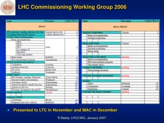
The Different Stages: Top Level Table for 7 TeV collisionsPhase A.5: 450 GeV only R. Bailey, 2006 Jan Uythoven, AB/BT
Details Stage A Above assumed damage limit of ~1e12 p+ at 450 GeV Jan Uythoven, AB/BT
Bunch Schemes 43 x 43 156 x 156 Up to 16 x 91010 = 1.41012 p+ /inj.:Injection around damage threshold Jan Uythoven, AB/BT
LHC Stage A: Commissioning phases Phases for full commissioning Stage A (pilot physics run) • First time that unsafe beam is being used: accent on Machine Protection issues • From here on not clear that phases will be done sequentially: can first do a ramp with pilot – at the edge of being unsafe at 7 TeV – before increasing intensity at injection • Can also have started two beam operation with pilots • Assume separation bumps are switched on all the time, crossing angles not needed for first collisions and not commissioned until 75 ns operation Jan Uythoven, AB/BT
Machine Protection System Commissioning Subgroup • Machine Protection Checks are obligatory and not ‘nice to have done’ • Working on detailed procedures in MPS Commissioning Subgroup, reporting to the LHCCWG: http://lhccwg.web.cern.ch/lhccwg/MPS/mps.htm Procedures being defined for all systems important for Machine Protection Follow up in MTF, identical to what is being done for the Hardware Commissioning This work is ongoing and the details of the MPS procedures are not finished yet Jan Uythoven, AB/BT
Objectives • Safe operation at 450 GeV with increased beam intensity: • Previous intensities used: single bunch of intermediate intensity or two pilots for LBDS timing commissioning • Ib < 31010 p+ • Target of this phase is 43 bunches with 41010 p+ per bunch • Ib < 1.71012 p+ : just above the safe limit at 450 GeV • Limit of this phase 156 bunches up to 91010 p+ per bunch • Ib < 1.41013 p+ : order of magnitude above the safe limit at 450 GeV • Repeat all commissioning steps for beam 1 and beam 2, sequentially • Intensity steps: slowly increase the injected and circulating intensity • Target • Increase number of bunches to 43 of 11010 p+ • Increase intensity per bunch up to 41010 p+ • Limit • Increase number of bunches to 156 of 11010 p+ • Increase intensity per bunch up to 91010 p+ • This will probably be interleaved with ramp commissioning • Parts of the described procedures can probably be done with two beams in parallel Jan Uythoven, AB/BT
How do we limit the LHC ? • Maximum intensity in the SPS can be “set” • Based on BCT reading • Half hardware – half software to set the maximum intensity • Used during TT40 / TT60 / TI 8 commissioning • ‘Commissioned Beam Envelope’ in the LHC • The maximum intensity of circulating beam in the LHC should agree with commissioned phases of the machine: ‘Commissioned Beam Envelope’ • Depends also on beam energy, *, n • The desired circulating beam intensity will be “programmed” via the sequencer and communicated via the timing system to the injector chain • Presently not (clearly) agreed upon check or control on this via any other system • Protection needed against • Failure in sequencer or timing system (hardware or software) • Human mistake made during the use of the sequencer • Could be injecting more beam than ‘allowed’ under certain conditions and not notice • Could be checked upon by software interlocks • Do we agree that this that this is sufficient? • If yes: We need to further specify this and agree who is doing this Jan Uythoven, AB/BT
Entry Conditions • Finished phase A1 - A4 successfully • Particularly important procedures from the previous phases: • Mechanical aperture of the machine known in numbers of sigma • A.4.5: Commission collimators and Protection devices • Assume that this is done in phase A.4: obligatory to have TCP protecting the aperture of the machine before going to 43 bunch mode: TCP at 5.7 • This way the TDI and TCDQ can be moved in without becoming a primary collimator • Procedures to set the collimators ‘repeated’ under A.5.6; can first be used with some pilots • TDI at roughly 10 (A.3.4.1.1), protecting against very big injection errors • Fine timing adjustments of dump system with 2 pilots beam (phase A.3.9.2.3) • Other entry conditions: • Complete hardware commissioning of LHC BIS finished successfully • Hardware commissioning tests of other important systems passed successfully • Vacuum, QPS, PIC, WIC, Experiments,… • Some interlocks which were masked with the Safe Beam Flag, will now need to be commissioned • Transfer lines TI 2 and TI 8 commissioned with intermediate beam intensities • Injection BIS completely hardware commissioned and commissioned with beam up to TI 8 downstream TED • Injection BIS in injection region commissioned without beam • Transfer line collimators not yet commissioned • Orbit feedback working (very much desired) • Beam requirements • Beam 1 and Beam 2 separately, easy change from one to the other • Single pilot or intermediate bunch, 43 bunches and 156 bunches • Nominal and reproducible beam emittance (value agreed for ramping) Jan Uythoven, AB/BT
Increasing Intensity at 450 GeV – Overview of Steps Involved Jan Uythoven, AB/BT
Beam Interlock System • The back bone of the Machine Protection System is the LHC Beam Interlock System • Its functionality will be fully tested without beam • Other Machine Protection System components will need to be tested without andwith beam • Most important components to be tested also with beam: • Injection System • LHC Beam Dumping System (LBDS) • Beam Loss monitors (BLMs) • Collimation System • This is also the time to bring the ‘additional safety systems’ into operation: • Fast Beam Current Change Monitor • Fast Beam Position Change Monitor Jan Uythoven, AB/BT
Orbit Feedback • In this phase an orbit feedback system will be extremely useful • For setting up the beam dumping system • For setting up the collimation system • To guarantee reproducibility • Should be able to easily deliver 0.5 stability • If the ‘real’ orbit feedback system does not work at this stage one can run “automatic orbit corrections” • Similar to what we did at LEP in the end • Correct every couple of minutes • The ‘real’ orbit feedback will be required for the energy ramp Jan Uythoven, AB/BT
Quenches • They might (already) start to occur in this phase and problems need to be understood and solved to be able to continue • If quenches occur • Reduce beam intensity (a bit) • Have to work on beam stability and collimators settings ‘earlier’ in this commissioning phase before ideal conditions have been reached • Might have to work on injection damper, cryogenics system, …. • Etc. Actions will need to be decided at the heat of the moment However, extreme care should be taken not to damage the machine After possible quenches are under control, can work through the commissioning program presented here Jan Uythoven, AB/BT
Detailed Steps A.5.1: Injection of 43 11010 Jan Uythoven, AB/BT
Detailed Steps A.5.2: Beam Dump I Jan Uythoven, AB/BT
Detailed Steps A.5.2: Beam Dump II * EMC more general (GA): keep statistics of number of (spurious) alarms as function of beam intensity… (TT40 experience) Jan Uythoven, AB/BT
Detailed Steps A.5.3: BDI and Beam Parameters Jan Uythoven, AB/BT
Detailed Steps A.5.4: BLMs Jan Uythoven, AB/BT
Detailed Steps A.5.5: Setting up the RF Jan Uythoven, AB/BT
Detailed Steps A.5.6: Collimators Protection settings of the arc by primary collimators was an entry condition. Now set-up the required cleaning by the collimators. Jan Uythoven, AB/BT
Collimators • There are collimators / protection devices with several functionalities • Betatron cleaning (IP7) • Momentum clearing (IP3) • Collimators for arc protection, triplet protection, … • Injection protection: TDI, TCDD and TCLI (injection system) • Dump protection: TCDQ, TCS and TCDS point 6 (beam dumping system) • The different functionalities can not be adjusted independently • Can not close TCDQ without the collimators in point 3 at some reasonable setting, giving a similar protection • In proposed procedure TCDQ and TDI always in the shade of TCPs: entry condition • Stable orbit required for setting up any of the collimators • Should be able to deliver something like 0.5 • Requirement around 0.4 (for two stage cleaning) • Stable optics required as well • Drift in beta beat below 8 % • Stability of dispersionbetter than 10 % in the H-plane • Stable beam sizes required • Emittance and local beta to be known • Bunch-to-bunch emittance variations can become an issue Jan Uythoven, AB/BT
Detailed Steps A.5.7: Injection of 43 41010 Jan Uythoven, AB/BT
Detailed Steps A.5.8: Checks with 43 41010 Jan Uythoven, AB/BT
Detailed Steps A.5.9: Safe Beam Flag Jan Uythoven, AB/BT
Detailed Steps A.5.10: Cryo and Vacuum Jan Uythoven, AB/BT
Repeat for 156 bunches of 1 - 4 -91010 • The details of the phases below are identical* to those already described for 43 bunches and will need to be repeated when going to 156 bunches: • first with bunch intensities of 11010 • followed by bunch intensities up to 41010 protons and then 91010 protons * Additional step A.5.15: Setting up the transfer line collimatorsreach dangerous beam levels at injection Jan Uythoven, AB/BT
Exit Conditions • Safe Operation with up to 1.41013 p+ at 450 GeV. Operation above the damage threshold • Multi-bunch injection, up to 16 x 91010 p+ commissioned and well tuned • Including cleaning and protection • Beam dumping system commissioned up to 1.41013 p+at injection • Collimators set-up for operation up to 1.41013 p+at injection • Settings entered in data base (centre, opening) • BLM loss pattern established • TCDI collimators in transfer lines just behind TED will need to be commissioned for operation with higher intensity 156 bunch operation • BI operational with up to 156 bunches and total intensity of up to 1.41013 p+ • RF adjusted for injection and circulating multi bunch operation Higher intensity beam under control and safe: we should not be quenching all the time…. Jan Uythoven, AB/BT
Summary and Discussion • Phase A.5 : • Increase beam intensity at 450 GeV above safe beam limit • For circulating beam maximum beam 1.4 1013 p+ • Also for injected beam: 16 x 91010 p+ = 1.4 1012 p+ • Main focus is on: • Machine Protection System • Many checks to take place during the Hardware Commissioning period, without beam: not presented here • Additional checks and set-up required with beam: presented here • ‘Control systems’ should be in an advanced phase and working according to their specifications • Sequencer, Management of Critical Settings, Software Interlock System, XPOC, Post Mortem etc. • System required to manage the ‘Commissioned Beam Envelope’ via measured operational parameters • Increasing the beam intensity will be a gradual, iterative process: • Same tests will need to be repeated every time the intensity is significantly increased above the already commissioned values • Also to be repeated when the bunch structure or optics is changed from the already commissioned values • Slowly gain experience of feedback systems, beam instrumentation, cryogenics etc. • Path of commissioning is not unique any more: • Could already have taken a pilot beam up the ramp • Could already have started two beam operation with pilots • Could already have collided pilot++ before finishing this stage Jan Uythoven, AB/BT
Spare slides Jan Uythoven, AB/BT
Peak energy deposition Edep in Cu vs beam sigma, for 450 GeV and 7 TeV protons Safe beam intensity vs energy, assuming 1e12 p+ is safe intensity at 450 GeV estimate Edep E1.7 (includes effect of emittance reduction) Pilot If assumed pilot safe at 7 TeV: Safe Beam intensity at 450 GeV : 5e11 p+ PILOT INTENSITY = SAFE BEAM INTENSITY @ 7 TeV