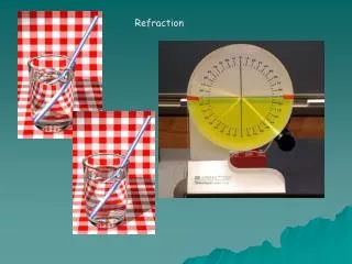
Atmospheric Refraction
Atmospheric Refraction. And Related Phenomena. Overview. Refractive invariant The atmosphere and its index of refraction Ray tracing through atmosphere Sunset distortions Green flash. Spherical Earth Approximation.


Atmospheric Refraction
E N D
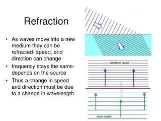
Presentation Transcript
Atmospheric Refraction And Related Phenomena
Overview • Refractive invariant • The atmosphere and its index of refraction • Ray tracing through atmosphere • Sunset distortions • Green flash
Spherical Earth Approximation For the purposes of this discussion, we will assume that the earth is a sphere • Earth is not really a sphere, but it is close enough for our purposes • Ray tracing using this model is very easy because there is a conserved quantity along the entire ray’s trajectory
Refractive invariant If there were no atmosphere, sin (z) = p/r r sin (z) = p where p is the distance of the ray’s closest approach. This quantity, p, is invariant for any point P along the ray.
Refractive invariant, cont For a ray entering a homogeneous atmosphere, n1 sin (z2) = sin (z1) n1 r1 sin (z2) = r1 sin (z1) = p But r1 sin (z2) = p1 , which is invariant along refracted ray. p = n r sin (z) (before and after refraction)
Refractive Invariant, cont For an atmosphere with 2 layers n2 sin (z4) = n1 sin (z3) n2 r2 sin (z4) = n1 r2 sin (z3) = n1 r1 sin (z2) = n1 p1 = p But r2 sin (z4) = p2 , which is invariant along refracted path. p = n r sin (z) (at any point along ray)
Refractive Invariant, cont • This process can be repeated for any number of layers with different index of refraction. • For any given ray, calculate p then solve for z: z (r) = arcsin (p/n(r)r) • if n(r)r is decreasing monotonically along ray’s path, z must be increasing monotonically 2 rays that converge on a point can never again cross • since sin(z) is symmetric about 90, if ray’s path has a minimum then it is symmetric about this minimum
Standard Atmosphere Model • based on meteorological data • temperature related to index, but only for lower 8-10 km • small contribution from upper layers of atmosphere
Trevor’s Model of Atmosphere • like the lower portion of standard atmosphere • specify: • ha (height of atmosphere) • ra (radius of earth) • ne (index at surface) • Gives index as a function of height n (r) = 1 + (r – re)(ne – 1)/h
Ray Tracing • Calculate p based on (x0,y0,θ0) • Calculate intersection of ray with next layer of atmosphere (x1,y1) • Calculate index, n1, at next layer based on model of atmosphere • Calculate new zenith angle, z1, using refractive invariant,p • Calculate θ1 • repeat steps 2-6
Ray Tracing, cont • Calculate p given (x0,y0,θ0) : P(t) = P0 + t v =[x0+t cos(θ0) , y0 + t sin(θ0)] x(t)2 + y(t)2 = r02 =x02 + y02 ta,b = 0 , -2(x0 cos (θ0) + y0 sin(θ0)) The ray is closest when t = tp = (ta+tb)/2 p=x(tp) 2 + y(tp) 2
Ray Tracing , cont • Calculate where ray intersects next layer of atmosphere at r1: P1(t) = P0 + t v =( x0+ t cos(θ0) , y0 + t sin(θ0) ) x(t)2 + y(t)2 = r12 ta,b = -((x0 cos (θ0) + y0 sin(θ0)) ± ((x0 cos (θ0) + y0 sin(θ0)) 2 – (x02+y02 -R12 ) P1 = ( x1 , y1 )
Ray Tracing, cont • Calculate index of refraction for next strata,n1, using n=n(r) • Calculate z1 using refractive invariant p p = n r sin(z) z1= arcsin (p/n1r1) • Calculate θ1 θ1 = z1 + arctan(y1/x1) - • Repeat steps 2-6
Ray Tracing Example • Ray tracing based on my model with n=1.05 at surface • notice that rays don’t cross
Ray Tracing Example 2 • Ray tracing based on my model with n=1.05 at surface • Notice that ray is symmetric about its minimum
Distortions of Sunsets • Position of sun • Angular size of sun • Rate of sun setting
Position and Angular Size of Sun • Rays traced using my model with n=1.00029 at surface, hatm=8 km, and actual sizes of earth and sun • Sun appears higher and smaller than it really is
Angular Size of Sun • Vertical size of sun • actual angular size of sun = 0.54 • at sunset, measured to be = 0.45 • at sunset, my model predicts size = 0.34 • Horizontal size • reduced by refraction because its extremities are both moved up towards the zenith on converging great circles, bringing them closer together • very small effect (approx 0.03%)
Rate of Sun Setting The speed at which the sun goes down is determined by: • the rate of rotation of the earth, d/dt = 360/(24*60*60 s) • the angular size of the sun = 0.54 • the latitude of the observer • the season (inclination of earth toward sun) • the effects of atmospheric refraction
Rate of Sun Setting, cont • plot shows the points where the top and bottom rays from sun set • angle between then
Rate of sun setting, cont On March 21 if there were no refraction the time for sun to set would be (at 50 lat): T = /(cos (θ) d/dt) = 197.5 s On March 14, I timed sunset to take T = 150 s My model predicts = 0.533 T = / d/dt = 127.9 s
The Green Flash • sun appears green just as it crosses horizon at sunrise and sunset • only seen if conditions are just right • there is a long history of wrong or incomplete explanations • refraction through waves • after image in eye after seeing red sunset • due mainly to: • differential refraction of different wavelengths • Rayleigh scattering • temperature inversion causing mirage
Differential Refraction • index of refraction varies slightly for different wavelengths of light nred = 1.000291 ngreen = 1.000295 nblue = 1.000299 • shorter wavelengths experience more refraction, thus set later than longer wavelengths
Differential Refraction Red light has set, but blue and green light is still above horizon
Rayleigh Scattering • light interacts with particles that are of similar dimension as wavelength of light • light absorbed then re-emitted in a different direction • air particles happen to be right size to scatter blue light • reason that sky is blue • light coming directly from sun that we see at sunset almost devoid of blue light • safe to look at sunset, as harmful UV rays are removed by scattering through thick slice of atmosphere
Basic Explanation of Green Flash • as red light (long ) from sun is just about to disappear, the blue and green light (shorter ) is still above horizon • the blue light has been removed by Rayleigh scattering, leaving green light This explanation is correct, but not complete. The effect it produces is 10X to weak to be seen with the naked eye. • Something else must be magnifying the green light to make it visible...
Mirages • Mirages are what is seen when light from a single point takes more than one path to the observer. The observer sees this as multiple images of the source object. • 2 basic types: • inferior mirage • superior mirage • Inferior mirage is what typically makes the green flash visible
Inferior Mirage • Occurs when temperature at surface is very high (low n) and observer looking down at heated region • rays bend upward toward the region of higher n upward • nr no longer monotonic, meaning rays below observer can cross, creating mirage sin(z)=p/nr • Green rays that have not yet set are bent toward observer • This is what makes green flash visible to naked eye