Download
1 / 28
360 likes | 940 Views
Adjustment of Triangulation. Introduction. Triangulation was the preferred method for horizontal control surveys until the EDM was developed Angles could be measured to a high level of accuracy Measured baseline distances were included every so often to strengthen the network.

E N D
Introduction • Triangulation was the preferred method for horizontal control surveys until the EDM was developed • Angles could be measured to a high level of accuracy • Measured baseline distances were included every so often to strengthen the network
Correction Term • Even if we use a full-circle arc tangent function we may still need a correction term • This can happen where the azimuth is near ±180° • Check the K-matrix term (measured minus computed) • If it is closer to ±360° than it is to 0°, correction is needed
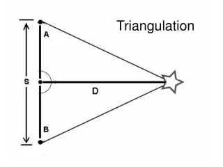
Set Up Matrices First, we need to define the Backsight, Instrument, and Foresight stations for the observed angles. angle B I F θ1 U R S θ2 R S U θ3 U S T θ4 S T U
J Matrix Note: Rho (ρ) is the conversion factor from radians to seconds. This complication can be avoided by keeping all angles in radian units (for example, in the K matrix).
K Matrix If this was in radians, we wouldn’t need Rho. Also, the second value should be zero. (why?)
Compute Solution and Update Coords Note: Further iterations produce negligible corrections.
Compute Statistics Residuals: V = J X - K S0
Other Angle Networks • Resection – more than 3 points is redundant • Triangulated quadrilaterals • Other geometric shapes