7E2: EM test plans
Gamma-ray Large Area Space Telescope. 7E2: EM test plans. GLAST Large Area Telescope: Tracker Subsystem. Nicola Mazziotta University and INFN Bari - Italy mazziotta@ba.infn.it. Outline. Test strategies First results Panel vib plan Tray thermal plan Tower vib plan Tower thermal plan

7E2: EM test plans
E N D
Presentation Transcript
Gamma-ray Large Area Space Telescope 7E2: EM test plans GLAST Large Area Telescope:Tracker Subsystem Nicola MazziottaUniversity and INFNBari - Italymazziotta@ba.infn.it
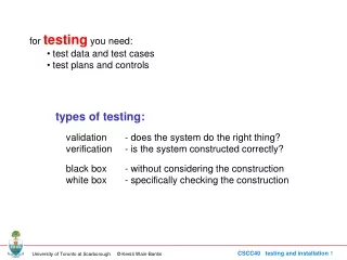
Outline • Test strategies • First results • Panel vib plan • Tray thermal plan • Tower vib plan • Tower thermal plan • EM Matrix plan • Reference LAT Documents: • LAT-MD-00408, LAT Instrument Performance Verification Plan • LAT-SS-00788, LAT Environmental Specification • LAT-TD-01005, Thermal Test Results on Thick Converter Mock-up Trays • LAT-TD-01249, Thermal Test Results for Pre-Engineering Model Trays • LAT-PS-01584, LAT Tracker TraySSD Ladder Panel Assembly Procedure • LAT-TD-01004, EM Tray Vibration Test Plan • LAT-TD-01037, EM Tray Thermal Test Plan
Tray factory (panels) Vibration test Ladder factory Tray assembly: ladders and MCMs on trays Thermal cycles Stacked cosmic rays* Electrical test Fast electrical test* Tower assembly Tray assembly&test sequence * Live trays
Tray vib levels White Noise Sine sweep Random vibration
Tray vib set up W side on the top • Accelerometers position: • Control: two mono-axial accelerometers positioned on two of the four L-shaped block TP1&TP2 • Fixture: three mono axial accelerometers placed on a corner on one of the four L-shaped block TP6 • Tray: one three-axial accelerometer in the middle TP5 • Centrotecnica set up: • - 1 LDS V864LTshake table • 2 fixtures • 9 read out channels • 4 trays/day test rate capability
First results – TG07 (1) Sine sweep before/after random Random vibration + White noise Z accelerometer response X accelerometer response Y accelerometer response Resonance search: 0= 815 Hz, Q 51 Resonance check: 0= 809 Hz, Q 49
Last Vib Runs (Mar, 17-19) (1) Light ≈1000Hz ≈660Hz ≈ 800Hz Heavy tray Mid tray
“Watch-dog” Last Vib Runs (Mar, 17-19) (2) Heavy tray (TS05) Q=100 @ 660Hz Output-expected: 140.4 grms Applied notching on qual ASD: output ≤ 16 g2/Hz ( Q=10) “Watch-dog” Input-notched: 13.6 grms Output-notched: 59.6 grms
EM Vib Runs Summary (16 trays) No relevant changes in the resonance frequency after the random All trays first mode › 500 Hz
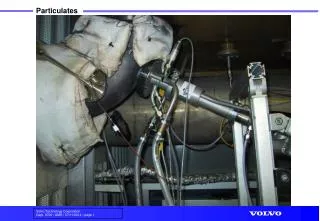
1 m3 Si Strain gauge Wheatstone bridge configuration (Labview) Reference Strain gauge on quartz Thermal tests on pre-EM trays: set-up Procedures: LAT-TD-1037; Pre-EM Results: LAT-TD-1249 Service box
Thermal tests on pre-EM trays: some results Stability @ plateau: dT/dt < 3°C/hr Tchamber Tsilicon Silicon temperature delay 45 min plateau 5 hr
Tray thermal levels T-C: Thermal cycle (dummy trays) T-V: Thermal vacuum (live tray) On orbit temperature range -15°C 30°C
Tray thermal sequence The EM dummy trays will be tested at ambient pressure into the service boxes
Tower vib levels Low frequency sine sweep White Noise Random vibration High frequency sine sweep
Tower vib set up • Accelerometers set up (TBR): • 3 axial on the shaker table (control accelerometer) • 3 axial on the center of the bottom tray lower surface • 3 axial on the center of the top tray upper surface • 3 axial accelerometer +X sidewall center of the thermal boss tray number 12; • 3 axial accelerometer +Y sidewall near the center of the tray number 10; • 3 axial accelerometer +Y sidewall center of the thermal boss of the tray number 1; • 3 axial accelerometer +Y sidewall center of the thermal boss of the tray number 19; • 3 axial accelerometer -X sidewall center of the thermal boss of the tray number 10; • 3 axial accelerometer -Y sidewall near the center of the tray number 10, on the center plane;
Tower vib sequence X,Y,Z axis For each axis
Tower thermal set up Tower covered with a thermal blanket during T-V cycles. The tower has a large number of thermocouples in the read out cables that can be acquired by using the TKR DAQ system. • Additional thermocouples (TBR): • +Y sidewall center of the thermal boss of the tray number 1; • +X sidewall center of the of the tray number 1, on the center plane; • +Y sidewall center of the thermal boss of the tray number 19; • +X sidewall center of the of the tray number 19, on the center plane; • -X sidewall center of the thermal boss of the tray number 10; • -Y sidewall near the center of the tray number 10, on the center plane The temperature control point for the cold part of the cycle will be the coldest thermocouple, while the control point for the hot part of the cycle will be the hottest one.