Download
1 / 7
70 likes | 517 Views
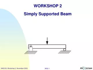
2D Modeling of the Deflection of a Simply Supported Beam Under Point or Distributed Loads. Yin-Yu Chen MANE4240 – Introduction to Finite Element Analysis April 28, 2014. Introduction/Background. Maximum deflection of a simply supported elastic beam subject to point or distributed loads

E N D
2D Modeling of the Deflection of a Simply Supported Beam Under Point or Distributed Loads Yin-Yu Chen MANE4240 – Introduction to Finite Element Analysis April 28, 2014
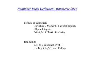
Introduction/Background • Maximum deflection of a simply supported elastic beam subject to point or distributed loads • M1 Abrams tank (67.6 short tons) equally supported by two simply supported steel beams • Land mine flush with the ground under the center of each beam • Determine the required height of the beam from the ground in order to avoid setting off the land mine • Moment-Curvature Equation
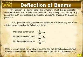
Analytical Formulation/Solution • Moment of Inertia of a Rectangular Cross Section of a Beam • Simply Supported Beam with Point Load at the Center • Simply Supported Beam with Uniformly Distributed Load
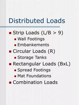
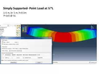
Modeling • COMSOL Multiphysics • 2D Structural Mechanics, Solid Mechanics and Stationary presets • Rectangular geometry with prescribed displacements of 0m at bottom corners (x & y for one, y only for the other) to represent a simply supported beam • Point load case: -300000N at center (x=4m) • Distributed load case: -37500N/m • Mesh Extension Validation • Extremely Fine • Finer • Normal • Coarser • Extremely Coarse
Results • Simply Supported Beam with Point Load at the Center • Simply Supported Beam with Uniformly Distributed Load
Results • Comparison of COMSOL Modeling/Numerical and Analytical Method Results • Comparison of ANSYS Modeling/Numerical and Analytical Method Results
Conclusions • Maximum deflection of a simply supported elastic beam subject to point or distributed loads may be achieved using either the modeling/numerical or analytical methods • Appears that the shape of the cells for the mesh is a major factor in the accuracy of the maximum beam deflection results • Quadrilateral cell mesh may offer the most accurate solution • The steel beam requires a minimum height of 0.2m from the ground for the tank to avoid setting off the land mine • This study highlights necessity for verifying the reliability of the approximate solution by comparing the results to: • A theoretical/exact solution • A different modeling approach • A mesh extension validation • If results from the COMSOL analysis of the uniformly distributed load across the beam were used without a factor of safety > 1.1 for the height of the beam from the ground, the maximum deflection due to the tank would set off the land mine