Download
1 / 39
540 likes | 796 Views
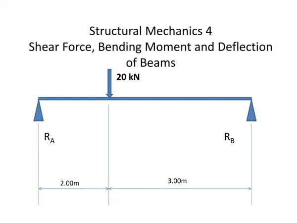
Deflection of Beams. (Credit for many illustrations is given to McGraw Hill publishers and an array of internet search results). Parallel Reading. Chapter 7 Section 7.1 Section 7.2 Section 7.3 Section 7.6 (Do Chapter 7 Reading Assignment Work).

E N D
Deflection of Beams (Credit for many illustrations is given to McGraw Hill publishers and an array of internet search results)
Parallel Reading Chapter 7 Section 7.1 Section 7.2 Section 7.3 Section 7.6 (Do Chapter 7 Reading Assignment Work)
Previously on Engr 350 Bending moments deflect beams along the arc of a circle. The degree of curvature depends on the magnitude of the Bending Moment, Young’s Modulus, and the beams Moment of Inertia
But as the Stomach Turns We Recently Learned that Bending Moments Vary over the Length of Beams We learned how to do bending moment Diagrams. But if the bending moment changes Over the length x, then the degree of Beam curvature must also be changing!
How Can We Get the Deflection of a Beam Under These Conditions? That curvature is the second derivative of vertical displacement at a distance x down the beam Time for some algebraic substitution! By algebra By substitution
Let Me See And I want this. y If I have this Oh Yes! How about integrating twice (Oh Gosh no – not calculus please)
Ok it May Suck But Lets Get to It If we integrate once We get the angle on the deflection curve. Or with substitution
If We Integrate Twice We can get the displacement of the beam
Dare We Try This? This is a cantilever beam with a simple end load. P Value of x M Our Moment Diagram L x L M=-P*x
Lets Integrate Once = -P*x
Houston – We Have a Problem I don’t see what c1 is The first integration gives us the bend angle
Off the Wall Boundary Conditions The angle of bend at the wall is 0. L X So when x = L Anyone going to give me genius credit for this?
Integrate Twice Slope Angle Integrate I get the equation for the elastic curve We have another unknown c (I feel a boundary condition coming on).
Checking Out the Wall L x What is the displacement at the Wall We better hope y=0 at x=L
Finishing Up Our Answer Get y by itself And when x = 0 y0
Assignment 22 Do Problem 7.3.5 Do Problem 7.3.16 Remember – Show and explain your work step by step. Scribbles with a circled Answer at the end – even if the answer is right, will be marked wrong.
We Can Well Imagine Some of the Loadings and Bending Moments We Might Face Could be Unpleasant Are We Always Going to Face Double Integrations with Boundary Conditions?
Not Necessarily As with most common integrals there is always someone making a standard table.
Lets Try Doing One With a Table Once upon a time there was a Uniformly loaded Cantilever Beam 100 lbs/ft 5.5 in δ 5.5 in (6X6 wood Beam) 12 ft We want the deflection distance δ
We Look Up the Solution On a Table The displacement at the end Of the beam.
Plug In Time Load = 100 lbs/ft = 8.33 lbs/inch Length 12 ft = 144 inches 3.35 in = 76.26 Young’s Modulus for Wood 1,750,000 psi (From Table F.2 in your Book)
But Lets Face ItYou Can’t Make a Table of Everything There are ways of extending basic tables to complex situations using the method of superposition. (Linear functions can be added one atop another to make some pretty complex stuff. How would you find the answer if you could?
The Need for Method of Superposition What are the chances I will find This situation in a table? I’ve got a bad feeling about that.
I Did See Some Stuff in the Tables that Relates Here is a set for a uniformly loaded beam Here is a point loaded beam
Lets Try a Cantilever Beam With A Uniform Load Only Over the Outer Half Tables Give Me a Uniformly Loaded Cantilever
So How Do I Get a Half Loaded Cantilever? We apply superposition
Of Course There Is a Problem If the tables don’t have half loaded cantilevers, how do I get a half loaded cantilever?
The Bending Moment Diagram Gives Us a Clue M How much of a bending moment did the maid in the parlor put on the outer end of that beam? 6 ft 12 ft You say None! So that outer part of the beam is not bent at all and only the inner nalf has anything to do with the problem.
Therefore We Can Start to Get One of Our Superposition Components from a half length cantilever. Displacement halfway out to the beam end is
Now for the Rest of the Story Because there is no bending the remaining half of the beam just keeps going straight up. But remember – we got the slope Angle from our first integration so That is bound to be in the table. Going up for a distance Of L/2
We Are Now Able to Give the Displacement for the cantilever with loading on the inner half
How Might the FE Test Our Mastery of Beam Deflections? What is going to happen with this load? A- That eccentric 50N load is going to twist the main rod B- The shear diagram will show that the 50N load will transfer and become a 50 N point load on the main rod which will act as a cantilever. We need to recognize that with Superposition we can solve each problem separately without interference from the other.
This is Just a Cantilever with a Point Load at the End 50 N 2 meters From a deflection table (or double integration like we did in class)
Going for a Quick Plug 50 N 2M We just need I for a Circular rod 3 cm Get Young’s Modulus From the problem
Moment of Inertia for a Circular Rod From tables such as those at the back of your Book. =3.976X10⁻⁸
And Finishing And Pick D!
Assignment 23 Do problems 7.3-18 7.3-21 Remember to explain and show step by step how you are solving these Problems. Putting down and answer with some scribbled steps does not Cut it and will get you marked wrong even if you chosen number or Expression is correct.