Download
1 / 12
120 likes | 263 Views
DCLL Thermal-Hydraulics. Edward Marriott University of Wisconsin-Madison FSNT Meeting August 18-20, 2009 UCLA. Outline. Goals Model Design ANSYS CFX Preliminary Results Simple Channel Simulation Future Work. Goals.

E N D
DCLL Thermal-Hydraulics Edward Marriott University of Wisconsin-Madison FSNT Meeting August 18-20, 2009 UCLA
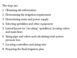
Outline • Goals • Model Design • ANSYS CFX • Preliminary Results • Simple Channel Simulation • Future Work EPM 8/18/09
Goals • Study the Helium flow distribution of the present design and adjust the design geometry to obtain an acceptable flow distribution everywhere. This will be performed with ANSYS CFX[1]. • Study the simulation of 2-D one-sided heat transfer enhancement of the First Wall and the corresponding increase in pressure drop. [1] http://www.ansys.com/products/fluid-dynamics/cfx/ EPM 8/18/09
Model Design • To analyze the Helium flow in ANSYS CFX it was required to create a solid model of the Helium volume itself. • This model was created in SolidWorks[2]. • The number of elements is limited in ANSYS so the full Helium volume was broken into sections, each will be analyzed in series. • For preliminary analysis, no steel structure will be included in the models. The steel structure can be added if necessary. • The different colors represent different sections of the model. There are 10 sections. [2] http://www.solidworks.com EPM 8/18/09
ANSYS CFX • ANSYS CFX allows the user to perform a simulation from geometry creation to post-processing without the need for other software. • Geometry can be created with the integrated ANSYS DesignModeler or geometries can be imported from external CAD programs such as SolidWorks. • Meshing can be completed using the CFX-Mesh utility within ANSYS CFX. • When the meshing is completed, then initial and boundary conditions can be established in CFX-Pre. This is the pre-processor portion of the simulation. • After the simulations have been run, the results can be analyzed in CFX-Post, which is a graphical post-processor. EPM 8/18/09
Preliminary Results • Preliminary analysis was performed to determine the capability of ANSYS CFX to accurately model the Helium flow. • Single Channel analysis is currently being performed. • Stage A (shown on the right) was simulated with an identical mass flow rate going to each “Helium Circuit.” • It can be seen that the flow is anti-symmetric at the first wall, which is a problem that is being worked on. EPM 8/18/09
Flow non-symmetry is due to non-symmetric First Wall inlet geometry EPM 8/18/09
Simple Channel Simulation of Surface Roughening • In the interest of applying ANSYS-CFX to simulate heat transfer coefficient enhancement a simple channel simulation is being performed. • One effect being studied is the change in heat transfer coefficient due to the application of roughness in the simulation. • The goal is to accurately create a result that gives at least h = 2*hsmooth - where hsmooth is the heat transfer coefficient from a smooth-walled simulation. • These results will be compared to 2-D roughened results with well defined geometry; increase of the friction factor will also be compared. EPM 8/18/09
Simple Channel Simulation • It is seen that an increase in wall roughness causes an increase in the heat transfer coefficient. • These results were compared to a calculation done with EES[3] to examine the trend exhibited by the change in heat transfer coefficient. [3] http://www.fchart.com/ees/ees.shtml EPM 8/18/09
ANSYS Wall Roughness • ANSYS CFX treats rough walls similar to smooth walls with the exception being that the logarithmic profile is moved closer to the wall. • Roughness effects are accounted for by modifying the expression for u+ as follows: where • We will learn if ANSYS CFX can be used or modified to approximate wall defined geometry roughening for both h and f. yR is the equivalent sand grain roughness. EPM 8/18/09
Future Work • Continue assessment of the Helium flow distribution and extend its assessment to the other sections of the Helium volume. Compare these results to those from CRADLE. • Continue to investigate the possibility of ANSYS CFX to simulate 2-D roughening and 2-D one-sided roughening of the first wall channel. It is likely that other methods of approximation will be needed. EPM 8/18/09