Networking Technologies Topologies
610 likes | 820 Views
Networking Technologies Topologies. Lesson 3 ( LO 1.2) Lecturer: Daniel K. Tom-Joe. Topology: Scope of Networks. Local Area Network. Wide Area Network. Segment. Terminator. Terminator. Bus Topology. Hub. Star Topology. Ring Topology. Mesh Topology. Star-Bus. Bus. Star-Ring.

Networking Technologies Topologies
E N D
Presentation Transcript
Networking TechnologiesTopologies Lesson 3 ( LO 1.2) Lecturer: Daniel K. Tom-Joe
Topology: Scope of Networks Local Area Network Wide Area Network
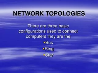
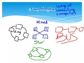
Segment Terminator Terminator Bus Topology
Hub Star Topology
Star-Bus Bus Star-Ring Hybrid Topologies
Characteristics Description Access Method CSMA/CD Transfer Speed Standard Ethernet – 10 Mbps Fast Ethernet – 100 Mbps Gigabit Ethernet – 1 Gbps (1000 Mbps) Ethernet Carrier Sense Multiple Access Collision Detection Transmits signal Detects signal Collision detected
Fiber Distributed Data Interface Secondary Ring Primary Ring Description Characteristics Access Method Token passing Fiber-optic at 155 Mbps to 622 Mbps Transfer Speed
Physical Ring Logical Ring MSAU Characteristics Description Access Method Tokenpassing Transfer Speed 4 to 16 Mbps for all cable types Token Ring A multistation access unit (MSAU) is a network hub in Token Ring local area networks (LANs).
Twisted-Pair Unshielded (UTP) Shielded (STP) 10BaseT Coaxial ThinNet ThickNet 10Base2, 10Base5 Fiber-Optics Network Cables Types of Cables
Infrared Transmission Narrowband Radio Transmission Wireless Communication Devices Wireless Communication Devices
Ethernet Token Ring Gateways Gateway
Wireless Communication by Using IrDA WindowsClient Laptop Mouse Infrared Data Association (IrDA)
Broadcast Unicast Multicast Types of Data Transmissions
IP Address Classes Class A Network ID Host ID Class B Network ID Host ID Class C Network ID Host ID w x y z
IP Address 192.168.1.100 IP Addresses 192.168.2.100 192.168.3.100 192.168.1.0 192.168.2.0 192.168.3.0 Network ID 192.168.1.100 192.168.2.101 Host ID
Subnet 1 Subnet 2 1 2 Hub Hub Router Subnets
Addressing Guidelines The First Number in the Network ID Cannot Be 127 The Host ID Cannot Be All 255s The Host ID Cannot Be All Zeros ( 00000. The Host ID Must Be Unique to the Local Network ID
IP Address 10 . 217 . 123 . 7 00001010 11011001 01111011 00000111 Subnet Mask 255 . 255 . 240 . 0 11111111 11111111 11110000 00000000 Number of Subnet Mask Bits (ones) 8 + 8 + 4 + 0 = 20 IP Address in CIDR Notation 10.217.123.7/20 CIDR Notation
Internet The Internet Server Text, Audio, Video, and Graphics Data Connection Using TCP/IP Protocol Client
Electronic Mail (e-mail) World Wide Web (WWW) Chat Internet News File Transfer Protocol (FTP) Telnet Internet Internet Services
Intranet Internet Extranet Intranets
URL (http://example.microsoft.com/tutorial/default.html) Protocol used (http://) DNS address (example.microsoft.com) Path on the server (/tutorial/default.html) http://example.microsoft.com/tutorial/default.html Uniform Resource Locator (URL)
Domain Name (example.microsoft.com) Top-level domain (com) Second-level domain (microsoft.com) Subdomain (example.microsoft.com) com microsoft.com example.microsoft.com Domain Naming
Domain Forest Domain nwtraders.msft Tree Domain Domain Domain Domain Tree namerica.nwtraders.msft samerica.nwtraders.msft Domain Organization
Single User Account Scalability Single Logon Centralized Management Features of a Domain
Paris Easy Location of Information Sales Repair User1 Computer1 User2 Printer1 Streamlined Access Delegated Authority Benefits of a Domain Organized Objects
HTTP HTTPS FTP SMTP NNTP HTML DHTML Internet Internet Protocols Server Data Connection Using an Internet Protocol Client
Application Layer Application Layer HTTP FTP Transport Layer Transport Layer TCP UDP Internet Layer Internet Layer IP ICMP IGMP ARP Network Interface Layer Network Interface Layer ATM Ethernet TCP/IP Layers
192.168.0.10 w2.x2.y2.z2 Web Server Web Browser Internet w1.x1.y1.z1 NAT Network Address Translators (NATs)
What is unshielded twisted pair, aka UTP, cabling? What are the twists for? CAT5 wiring for networks
Category 3 – Telephone Cable or 10 Mbps data Category 5 – 10/100 Mbps Category 5e – 10/100 Mbps or 1000 Mbps (1 Gbps) for short distances Category 6 & 7 – 10/100/1000 Mbps Categories of UTP
Straight through Used to connect computers to switches or routers to switches Crossover/cross connect used to connect a computer to another computer or a switch to another switch Roll/rollover cables Used to connect to a console port on managed switches or routers Types of cables
Crimp Tool Cable Stripper (Cyclops) Cat 5 or 5e UTP cable RJ-45 – Cat-5e modular plugs Cable tester Tools & Materials for Making Patch Cables
Not all wires made a connection Wires were in the wrong order Too much of the cabling jacket was cut off Wires were untwisted too much, causing interference between wires. What kinds of things can go wrong when making a a cable?
What kinds of things can go wrong when making a a cable? • Construction problems
Wiring order is mixed up or open Crossed Pairs – The twisted wires are still paired, but you mixed up the correct order of the wire pairs. Reversed Pair – The reversed-pair fault occurs when a wire pair is correctly installed on one connector, but reversed on the other connector. This is also called a polarity reversal or tip-and-ring reversal. Split Pairs – A split-pair wiring fault occurs when one wire from one pair is switched with one wire from a different pair at both ends. This mixing hampers the cross-cancellation process and makes the cable more susceptible to crosstalk and interference. Open Pair – Lack of continuity between pins at both ends of the cable on one or more wires. There is no path to carry electrical signals. What kinds of things can go wrong when making a a cable?
Pin outs - Why do we need standards? No matter what wiring order you use, a cable will work as long as the other end is wired in the same order. Many networking professionals, particularly those who were self taught, had their own wiring orders they used. However, wiring pairs may not be kept together. This is bad because twisted pair cabling use the twists in the wires to control noise. This is a simplified way of thinking of how it works. Both wires receive the same noise; what is received on the reference is subtracted from the other. This can dramatically affect performance Sometimes, you work on one end, but you were not the one who wired the other end. You expect it to be wired a certain way. The order means something. The standard was published in 1991 to create a multiproduct, multivendor, standard for connectivity. Prior to the adoption of this standard, many "proprietary" cabling systems existed. This was very bad for the consumer. Two main standards for UTP – 568A and 568B 568A is most commonly used by the telecommunications industry 568B is most commonly used in data networks Wiring Order for Cat5 Cable Crimps
Patch Cable Assembly Instructions 1. Skin off the cable jacket approximately 1" or slightly more.2. Un-twist each pair, and straighten each wire between the fingers.3. Place the wires in the order of one of the two diagrams shown above (568A or 568B). Bring all of the wires together, until they touch.4. At this point, recheck the wiring sequence with the diagram. http://www.lanshack.com/make-cat5E.aspx
Patch Cable Assembly Instructions 5. Optional: Make a mark on the wires at 1/2" from the end of the cable jacket. 6. Hold the grouped (and sorted) wires together tightly, between the thumb, and the forefinger. 7. Cut all of the wires at a perfect 90 degree angle from the cable at 1/2" from the end of the cable jacket. This is a very critical step. If the wires are not cut straight, they may not all make contact. We suggest using a pair of scissors for this purpose. 7B. Conductors should be at a straight 90 degree angle, and be 1/2" long, prior to insertion into the connector. 8. Insert the wires into the connector (pins facing up). Making patch cables
Patch Cable Assembly Instructions (cont.) 9. Push moderately hard to assure that all of the wires have reached the end of the connector. Be sure that the cable jacket goes into the back of the connector by about 3/16". 9. Place the connector into a crimp tool, and squeeze hard so that the handle reaches it's full swing.10. Repeat the process on the other end. For a straight through cable, use the same wiring. For a "crossover" cable, wire one end 568A, and the other end 568B.11. Use a cable tester to test for proper continuity.
Straight through Used to connect computers to switches or routers to switches 568B on one end to 568B on the other 568A on one end to 568A on the otherCrossover/cross connect used to connect a computer to another computer or a switch to another switch 568B on one end to 568A on the other Wire Order for Types of cables
Notes Regarding Making Category 5 Patch Cable The RJ-45 plugs are normally made for either solid conductors or stranded conductors. Using the wrong type can possibly cause intermittent problems. Ordinarily, it would be taboo to untwist the pairs of any category 5 cable. The one exception to this rule is when crimping on RJ-45 plugs. It would be impossible to insert the wires into the channels without first untwisting and straightening them. Be sure not to extend the un-twisting, past the skin point. If you do it properly, you will wind up with no more than 1/2" of untwisted conductors (up to 1/2" of untwist meets the cat 5 specification). If the completed assembly does not pass continuity, you may have a problem in one, or both ends. A good cable tester may tell you which end is faulty. First try giving each end another crimp. If that does not work, then carefully examine each end. Are the wires in the proper order? Do all of the wires fully extend to the end of the connector? Are all of the pins pushed down fully? Cut off the suspected bad connector, and re-terminate it. If you still have a problem, then repeat the process, this time giving more scrutiny to the end that was not replaced. Making UTP connections
The technical answer is … it depends. If you are using 10BaseT or 100Base-TX, it may work. However you are taking a RISK of damaging equipment in certain types of installations. If you do wire your network this way, you may have to re-wire later to prevent problems. Increasingly we are seeing 'Power-over-Ethernet (PoE)' systems which can make use of both spare pairs in 1000base-TX wiring and will likely provide power for VoIP or other technologies. If you mix PoE systems with non-standard wiring you could destroy or damage equipment and have other unpleasant or harmful effects. 1000base-T (gigabit Ethernet) uses all 4 pairs (8 conductors) and cannot be used with mixed LAN and telephony wiring. Bottom line – You are taking a chance when you mix LAN and telephone connections on the same cable. Can I run a LAN and telephones on the same LAN cable?
What is a patch panel? Below you can see a patch panel for data networks. Punching down UTP connections in Patch Panels
What is a patch panel? RJ-45 on one side, 110 punch down block on the other side What is a punching down block? connecting communications conductors is at a multi-terminal assembly of self-stripping, crimp connections 66 vs. 110 blocks 66 blocks are for voice conductors 110 blocks are for data conductors. We use patch panels and punch-down blocks to facilitate testing and provide for additions and modifications to the cable plant (cabling system). The outlet itself is almost always one or two RJ-45 jacks you mount on a single-gang plate. (The RJ-45 is the 8-pin modular phone plug. Universally, we use it for data networks.) Punching down UTP connections in Patch Panels
It's important to leave enough extra cable at each outlet point. The recommended lengths are a minimum of 10 feet in the telecommunications closet for both twisted-pair, and 12 inches for twisted-pair cable at the outlet. Don’t stretch the cable too tight Leave a small loop of cable for alterations Do not nick the wire when stripping What is punching down for?
110 Punch down tool 110 blade Patch panel or jack Cable Stripper Cable Wire cutter Cable Tester Tools for Punching Down