Network Topologies
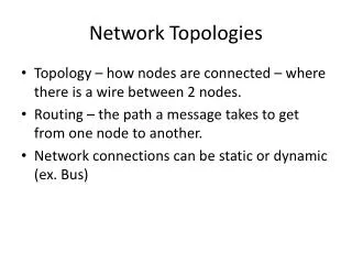
3-19. Network Topologies. T. T. Free Topology . 3-20. Ring, star or combination layout of network media All except ring are polarity insensitive One terminator installed anywhere on the segment Typical for device channels May be difficult to troubleshoot bad devices

Network Topologies
E N D
Presentation Transcript
3-19 Network Topologies
T T Free Topology 3-20 • Ring, star or combination layout of network media • All except ring are polarity insensitive • One terminator installed anywhere on the segment • Typical for device channels • May be difficult to troubleshoot bad devices • Installers could possibly exceed wiring limits • Simple to expand and add new devices
T T Bus Topology 3-21 • Daisy chain structure with beginning and end • Must be terminated at beginning and end of segment • TP/FT-10 Free Topology terminators are different from TP/FT-10 Bus Topology terminators • TP/XF-1250 channels use different terminators than TP/FT-10 channels • Compared to Free Topology: • Easier to troubleshoot • Longer cable runs allowed • More difficult to expand and add new devices
Backbone Topology 3-22 • Connects routers to a common backbone channel • Typically installed in a bus topology and includes routers, tool network interfaces, and system wide controllers • Can be high speed twisted pair TP/XF-1250 or IP-852 channel • Reserves bandwidth for network tools and system control devices such as web servers, data loggers, schedulers, alarm generators, etc. Termination will depend upon typology used on specific segments
Case Study Exercise:Identify Network Architectures 13-23 Turn to the Laboratory Exercises chapter of your workbook – this is Laboratory 1 • Form a team with one or two fellow students • Read exercise instructions • Write down your answers • Class review follows in 20 minutes
3-24 Installation Scenarios
Engineered Design – Planned Installation Scenario 3-25 • Design tool is not attached to the network devices during design process • Tools obtain device information from the device external interface file (xif) • Allows network design to be completed in parallel with infrastructure installation • Verifies device compatibility prior to purchasing • Allows distribution of design workload
Ad Hoc Installation 3-26 • Design tool is attached to the network devices while the design is created • Tools can upload the device interface information from the device • Use this method if XIF file is not available • Typical for small networks • Design should be created while the tool is OffNet to minimize traffic consequences from updating device information
Matching the Design with the Physical Network 3-27 • The logical device on the design must match the physical device installed on the network. • The network tool first identifies the network device using the device’s unique Neuron ID • Service Pin depression • Manual entry • Device discovery • The match is completed using the device’s channel and program ID
Job Aids 3-28 • Guide for Determining Installation Scenario • Network Tool Selection Guide
Selecting a Network Tool 3-29 • Should be based on the user and project’s needs • Available from many manufacturers • Tools should include the latest LONMARK resource files documenting SNVT, SCPT and SFP • Tools should perform multiple functions • Network design and engineering • Network commissioning and configuration • Network monitoring and control • Network maintenance and documentation • Must be able to support up to 32,385 devices and domain addresses of up to six bytes (248) • While not required for an open system, tools based on LNS provide • Interoperability and connectivity features • Capability to integrate LONMARKdevices
Summary and Review 3-30 • Do remote clients include the LNS network database? No • What has a data server allowing it to communicate directly with devices through its own network interface? Fullweight client • What is required by LNS tools to perform network management tasks The LNS database • Which topology is easier to troubleshoot and allows for longer cable runs? Bus • Which channel type can take advantage of existing IP infrastructure? IP-852 • How many devices must a network tool be able to support? What size domain address? 32,385, 248 (six bytes)
Selecting Infrastructure Components
PLAN THE NETWORK Identify Architectures Select Network Components IMPLEMENT THE NETWORK Install Physical Network Program Network Commission Network TEST AND OPTIMIZE Test and Verify Network Optimize Network DOCUMENT AND MAINTAIN Document Network Maintain Network Objectives 4-2 • Define the infrastructure components of a LONWORKS network • Select network media • Define the metrics and channel characteristics of channels • Select appropriate network interfaces • Select LONWORKS routers and repeaters • Describe the difference between a router and a repeater
NI RPTR RTR RTR RTR RTR Main Infrastructure Components 4-3 • LONWORKS Devices1 • Communication Channels • Communications media that connect LONWORKSdevices • Path between devices that exhibits various physical characteristics. • Routers1 and Repeaters • Used to build large networks by connecting channels and segments • Routers also used to transfer data from one channel type to another • Network Interfaces1 • Connect PC to LONWORKSnetwork • Also referred to as LonTalk adapter or LonTalk interface 1Most commonly specified components
Channel W Domain 09E Segment A 1 2 3 4 61 62 63 Subnet 2 Backbone Channel RPTR RTR RTR RTR RTR Physical vs. Logical (1) 4-4 Neuron ID • Unique 48 bit ID embedded into Neuron Chip Segment • Section of physical media connected to router or repeater port • Unpowered TP/FT-10 can support up to 64 devices Channel • Representation of physical media segment(s). • Connected to other channels via routers • Characterized by device transceiver types • Can consist of two segments linked via physical layer repeater Channel X Segment C Segment B 1 2 62 124 1 2 3 Subnet 1 Subnet 3 Channel Z Channel Y Segment E Segment D 1 2 3 1 2 55 56 Subnet 4 Subnet 5
Channel W Domain 09E Segment A 1 2 3 4 61 62 63 Subnet 2 Backbone Channel RPTR RTR RTR RTR RTR Physical vs. Logical (2) 4-5 Logical Address Assigned by NI Tool Domain, Subnet, Node Example 09E, 2, 63 Logical addresses are assigned during commissioning to enable devices to become active participants on network Node ID • A logical address assigned to device Domain • A logical collection of up to 32,385 devices (nodes) on one or more channels • Can include up to 255 subnets • Direct communications can only take place among devices configured in the same domain • ID can be 1, 3 or 6 bytes (248) long Subnet • A logical organization of up to 127 devices • Some channels may include more than one • Cannot span configured or learning routers Channel X Segment C Segment B 1 2 62 124 1 2 3 Subnet 1 Subnet 3 Channel Z Channel Y Segment E Segment D 1 2 3 1 2 55 56 Subnet 4 Subnet 5
Possible LONWORKSMedia Types 4-6 • Twisted Pair Cable • LONMARK Guidelines supports both TP/RS485-39 and TP/FT-10 • TP/FT-10: low material cost, reduced cabling, high stability • Twisted Pair Cable with Link Power • Power and Communication on single pair of wires • Power Line • Reliable communications over existing power wires • No additional cable or installation interruption, limited range, 5400 bps • IP (Internet or Intranet) • High transfer rate • Can use existing IP infrastructure • Fiber Optic • Highest transfer rate in rough (noisy) environments over long distances • Radio Frequency • Communicate with remote locations without cabling • Infrared • Electric Fencing
Channel Metrics 4-7 max node count max node-to-node distance • Topology support: free, bus or other • Maximum length • Maximum device count • Maximum number of packets/sec • Cable type: standard or special • Termination requirements • Private or shared media min node distance n stub length 2 1 pkt/s max length
PL-20x TP/FT-10 TP/XF-1250 IP-10x Typical Channel Capacities pps: packets per second (average packet = 15 bytes) IP-852 estimate based on 46 byte minimum payload
Job Aids 4-8 • Common LONWORKS Channel Types • Miscellaneous Channel Types • LONMARK Standard Channel Types
Connects channels or subnets to build large networks or reduce traffic Can connect different channel media types Filters or forwards messages based on Subnet ID or Domain ID (bridge) to provide network segmentation Can be configured as repeater to extend channel length Can be setup as learning, configured or bridge Channel 2 FT-10 Router Channel 1 IP-852 LONWORKS Routers 4-9 • Bridge used to isolate packets within networks that include multiple network domains • Learning router automatically builds its own filter table by monitoring traffic
Router and Physical Layer Repeater Differences 4-10 While both provide signal refresh, LONWORKS Routers… • Segment or isolate local traffic (primary function) • Connect similar or different channel types • Forward packets based on internal routing tables of subnet and group addresses maintained by LNS • Can be configured as an intelligent repeater Physical Layer Repeaters… • Extend channel distance by amplifying signal • Allows for higher device counts • Have no filter function and dispatch each message as received • Pass all traffic – even noise • Can lead to channel overload LONMARK Guideline The total network length and number of devices may be extended by use of ANSI/EIA/CEA-709.1 routers, and/or one TP/FT-10 physical layer repeater.
Routing Design Guideline IP-852 IP-852 i.LON Router i.LON Router FT-10 FT-10 XF-1250 LPR-12 LPR-12 For best performance always route from slower to higher speed channels XF-1250 Improved Design – Route from slow to fast Poor Design – Slower channel between faster channels
Multiple XF-1250 Channel Routing IP-852 IP-852 i.LON Router i.LON Router i.LON Router XF-1250 XF-1250 LPR-15 Potential Bottleneck XF-1250 Improved Design – i.LON routes at full speed of XF-1250 channel XF-1250 Poor Design – LPR-15 throughput less than single XF-1250 channel
Large System Routing IP-852 IP-852 i.LON Router i.LON Router XF-1250 FT-10 (or individual LPR-12s) MPR-50 LPR-10 FT-10 LPR-10 FT-10 FT-10 FT-10 LPR-10 FT-10 FT-10 Improved Design – Eliminates hops across slower channels FT-10 Poor Design – Too many router hops across slower channels
Network Interfaces 4-14 • Connect PC to LonTalk medium • Also referred to as network adapters and LonTalk interfaces • Available in almost any PC form-factor, transceiver type and bus configuration • Must support NSI (Network Services Interface) firmware for LNS applications • Should support downloadable firmware images to allow for easy LNS firmware updates • IP – virtual network interface (VNI) or remote network interface (RNI) • VNI creates a high performance IP-852 network interface with greater throughput than NSI. • RNI provides a remote IP network interface Network Tool Which NSI ?
PCI PCLTA-21: FT-10, TP-78, TP-1250, RS-485 PCLTA-20: TP-1250 SMX PCMCIA PCC-10: FT-10, TP-78, TP-1250 EIA-232 STLA-10: FT-10, TP-78, TP-1250, RS-485 i.LON 100 i.LON SmartServer Modem FT-10, PL-20 (Modem Option) USB U20: PL-20 U10: TPFT-10 i.LON SmartServer i.LON 600 i.LON 100 i.LON 10 10/100 Ethernet IP/RNI FT-10,PL-20 FT-10,XF-1250 FT-10,PL-20 FT-10,PL-20 i.LON 600 i.LON 100 i.LON SmartServer IP-852 Routing (Router Option) Modbus IP i.LON SmartServer Connectivity Options 4-15
Summary and Review 4-16 • What are the most commonly specified components in a LonWorks network? LonWorks devices, router and network interface • How many devices can a subnet support? How many can an unpowered TP/\FT-10 segment support? 127, 64 • Which channel type can provide the highest transfer rate in noisy environments over long distances? Fiber optic • What can segment or isolate local traffic and connect similar or different channel types? Routers • True or false: LonMark Guidelines supports RS485 for use on twisted pair. True. RS-485 is supported as TP/RS485-39
Installing the Physical Network
Objectives 5-2 • Define infrastructure installation tasks • Select and install channel media • Decide where and when to use terminators for twisted pair channels • Identify common installation pitfalls • Describe guidelines for installing channel topologies: • Properly install shielded cable • Describe device installation guidelines
PLAN THE NETWORK Identify Architectures Select Network Components IMPLEMENT THE NETWORK Install Physical Network Program Network Commission Network TEST AND OPTIMIZE Test and Verify Network Optimize Network DOCUMENT AND MAINTAIN Document Network Maintain Network Installation Tasks 5-3 • Install backbone channel • Install device channels and routers • Install terminators where needed • Mount and install devices • Provide power supplies to devices • Connect I/O wiring to devices Most LONWORKSnetwork problems can be traced back to an inadequate installation of cables and devices.
Cabling Installation 5-4 • Use Echelon tested cable types • Match cable length limitations to transceiver type and channel topology • For link power transceiver devices (LPT-11), size wire to accommodate 42 VDC voltage drops over distance • Size distributed power cable to accommodate voltage drops over distance • Avoid magnetic inductive interference when laying cables • Keep nominal distance from AC cables • Separate from RF and high voltage sources (low voltage sources okay) • Maintain “twisting” to terminal • Keep away from devices and actuators that generate strong interference • Use lightning-current arrestor needed anytime twisted pair goes outside building • Follow local and national regulatory requirements
When using shielded cable, terminate shield using the recommended grounding circuit Ground the cable shield at least once per segment and preferably at each device Grounding the shield at every device will assist in suppressing 50/60Hz standing waves. Communication wires are not grounded Shielded cable not recommended unless in high EMI environment. Grounding Shielded Twisted Pair Cable 5-6
Job Aids 5-7 • Cabling Installation – Procedures • Cabling Installation – Common Pitfalls • Miscellaneous Infrastructure Components
TP/FT-10 TP/LP-10 TP/LP-11 Channels 100 mF 52.3Ω Free Topology 105Ω Bus Topology 100 mF TP/XF-78 TP/XF-1250 Channels 0.15 mF 59Ω 0.33 mF 340Ω Power Line Channels 0.47 mF 102Ω 100Ω Termination: What is it? 5-8 • A termination is a load connected across the network pair • Termination absorbs unwanted signal reflections (resonance of date signal) which would interfere with communications causing packet errors • Free topology uses one terminator anywhere on segment • Bus topology uses two terminators one at each end of segment • Verify termination for unknown twisted pair media by checking wiring impedance using an AC bridge
Device Installation 5-9 • Mount devices as close to I/O as possible • Where possible, avoid high EMI sources • Install application specific devices on application specific channels • Isolate device to device traffic where possible • Use routers for each subsystem • Install fewer than maximum allowed to provide for future expansion • Locate system-wide control devices and network tools on or close to the backbone • Web server devices, trend loggers, schedulers, etc…
LPT Link Power - Power and Communication on TP/FT-10 5-10 • LPT Link Power devices draw power from central 42V power supply on TP/FT-10 channel eliminating need for individual device supplies • Link power transceiver separates 78 kbps communication and 42 VDC power to supply +5VDC at up to 100mA to Neuron and I/O applications • Both link power and locally powered TP/FT-10 devices can be supported on a given segment, provided that the following constraint is met: (1 x LPT) + (2 x TP/FT) ≤ 128 • TP/FT-10 devices must be designed to ISO/IEC 14908-2 (ANSI/CEA-709.3) which specifies appropriate blocking capacitors • Considerations • The sum of the application current of all the devices in a segment must not exceed 3.2A on 5V supply. • Voltage at LPT supply typically 41.0 to 42.4V • Voltage at end of cable must not be less than 26V - LPT transceiver lower limit • Actual number of devices on segment depends upon cable length and current • Example: 500 meter Beldon 8471 and 85102 support 128 evenly distributed LPT devices at 25mA, 64 at 50mA or 32 at 100mA
Job Aids • Junction Box and Wiring Guideline for Twisted Pair LONWORKS Networks • FTT-10A Free Topology Transceiver User's Guide • LPT-10 and LPT-11 Link Power Transceiver User’s Guides These job aids are on your student CD. Most recent versions on the Echelon Web site.
Summary and Review 5-12 • What can most LonWorks network problems be traced back to? Inadequate installation of cables and devices • How can you avoid magnetic inductive interference when laying cables? Keep nominal distance from AC cables . Separate from RF and high voltage sources. • What must be used anytime twisted pair cable goes outside of a building? Lightning-current arrestor • How many terminators are required on a twisted pair free topology segment? Bus topology? Where should they be installed? Free: One, anywhere on segment. Bus: Two, one at each end of segment. • How many non-link powered devices can be added to a segment which already has 56 link-powered devices? 36 (128 – 56) / 2 • Where and how should shielded cable be grounded? At minimum once per segment, preferably at each device
Exercise: Selecting and Installing Infrastructure Components 5-13 Turn to the Lab 2 in the Laboratory Exercises chapter of your workbook • Form a team with one or two fellow students • Read exercise instructions • Find answers • Lab discussion and class review follows in 20 minutes
Describe the principles of LONWORKS networks Select network architectures and design strategies Determine installation and maintenance scenarios Select channel types, infrastructure devices, application devices Install the physical network infrastructure Review
L1-1 HMI Tool NM Tool PSTN Modem NM Tool SLTA-10 NSI Lab 1, Case Study 1