Download
1 / 4
40 likes | 83 Views
This paper describes the "Design and Implementation of Tongue Motion Controlled Wheelchair"u009d. Most serious accidents and injuries often end with various motorist disabilities usually resulting in a limited control of the muscles of various body parts and in some worst case scenarios even the whole body. Tongue driven system is a new wireless assistive technology for persons severely disabled due to spinal cord injuries, quadriplegia or repetitive strain injuries RSI . It translates the user's intensions into control commands by detecting and classifying their voluntary tongue movements. Tongue driven system consists of an array of hall effect magnetic sensors and permanent magnet which is held on tongue using tissues adhesive and tongue piercing. An array of magnetic sensor is mounted on the headset outside the mouth. The RF module is used for wireless technology and AT mega328 is used as a controller. The sensor's output is wirelessly transmitted to the microcontroller and it will process the signal to control the movement of power wheelchair. Two DC motors are used to drive the wheelchair. This technology provides faster advanced smoother and more convenient control. Moe Myint Aung | Yu Yu Mon Win | Khin Su Hlaing "Tongue Motion Controlled Wheelchair" Published in International Journal of Trend in Scientific Research and Development (ijtsrd), ISSN: 2456-6470, Volume-3 | Issue-5 , August 2019, URL: https://www.ijtsrd.com/papers/ijtsrd25286.pdf Paper URL: https://www.ijtsrd.com/engineering/electronics-and-communication-engineering/25286/tongue-motion-controlled-wheelchair/moe-myint-aung<br>

E N D
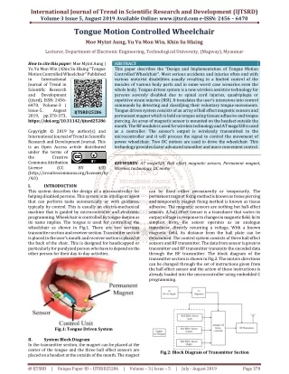
International Journal of Trend in Scientific Research and Development (IJTSRD) Volume 3 Issue 5, August 2019 Available Online: www.ijtsrd.com e-ISSN: 2456 – 6470 Tongue Motion Controlled Wheelchair Moe Myint Aung, Yu Yu Mon Win, Khin Su Hlaing Lecturer, Department of Electronic Engineering, Technological University, (Magway), Myanmar How to cite this paper: Moe Myint Aung | Yu Yu Mon Win | Khin Su Hlaing "Tongue Motion Controlled Wheelchair" Published in International Journal of Trend in Scientific Research and Development (ijtsrd), ISSN: 2456- 6470, Volume-3 | Issue-5, August 2019, pp.370-373, https://doi.org/10.31142/ijtsrd25286 Copyright © 2019 by author(s) and International Journal of Trend in Scientific Research and Development Journal. This is an Open Access article distributed under the terms of the Creative Commons Attribution License (CC (http://creativecommons.org/licenses/by /4.0) I. INTRODUCTION This system describes the design of a microcontroller for helping disabled persons. This system is an intelligent agent that can perform tasks automatically or with guidance, typically by control. This is usually an electro-mechanical machine that is guided by microcontroller and electronic programming. Wheelchair is controlled by tongue motion as its name implies. The tongue is used for controlling the wheelchair as shown in Fig.1. There are two sections transmitter section and receiver section. Transmitter section is placed in the user’s mouth and receiver section is placed at the back of the chair. This is designed for handicapped or particularly for paralyzed person who have to depend on the other person for their day to day activities. ABSTRACT This paper describes the “Design and Implementation of Tongue Motion Controlled Wheelchair”. Most serious accidents and injuries often end with various motorist disabilities usually resulting in a limited control of the muscles of various body parts and in some worst case scenarios even the whole body. Tongue driven system is a new wireless assistive technology for persons severely disabled due to spinal cord injuries, quadriplegia or repetitive strain injuries (RSI). It translates the user’s intensions into control commands by detecting and classifying their voluntary tongue movements. Tongue driven system consists of an array of hall effect magnetic sensors and permanent magnet which is held on tongue using tissues adhesive and tongue piercing. An array of magnetic sensor is mounted on the headset outside the mouth. The RF module is used for wireless technology and AT mega328 is used as a controller. The sensor’s output is wirelessly transmitted to the microcontroller and it will process the signal to control the movement of power wheelchair. Two DC motors are used to drive the wheelchair. This technology provides faster advanced smoother and more convenient control. KEYWORDS: AT mega328, Hall effect magnetic sensors, Permanent magnet, Wireless technology, DC motor IJTSRD25286 BY 4.0) can be fixed either permanently or temporarily. The permanent magnet fixing method is known as tissue piercing and temporarily magnet fixing method is known as tissue adhesive. The magnetic sensors are nothing but hall-effect sensors. A hall effect sensor is a transducer that varies its output voltage in response to changes in magnetic field. In its simplest form, the sensor operates as an analogue transducer, directly returning a voltage. With a known magnetic field, its distance from the hall plate can be determined. The control system consists of three hall effect sensors and RF transmitter. The data from sensor is given to transmitter and RF transmitter transmits the encoded data through the RF transmitter. The block diagram of the transmitter section is shown in Fig.2. The motors directions can be changed through the set of instructions given from the hall effect sensor and the action of these instructions is already loaded into the microcontroller using embedded C programming. Fig.1: Tongue Driven System II. In the transmitter section, the magnet can be placed at the center of the tongue and the three hall effect sensors are placed on a headset at the outside of the mouth. The magnet System Block Diagram Fig.2: Block Diagram of Transmitter Section @ IJTSRD | Unique Paper ID – IJTSRD25286 | Volume – 3 | Issue – 5 | July - August 2019 Page 370
International Journal of Trend in Scientific Research and Development (IJTSRD) @ www.ijtsrd.com eISSN: 2456-6470 The RF receiver provides the information to the microcontroller from RF transmitter and the controller judges whether the instruction is right movement or left movement based on the tongue movement and controls the direction. Two DC motors are used for the movement of wheelchair. The block diagram of the receiver section is shown in Fig.3. At the transmitter side, the pins are configured initially. Then, the hall effect sensors will be read. If the sensors is sensed the data, the required data will transmit. Otherwise, hall effect sensors are read again. If the sensors is not sensed the data, the data transmission will be stopped. Fig.4 shows flowchart of transmitter section of the system. At the receiver side, initially, the pins are configured. Then, the serial data from RF transmitter module is read. If RF transmitter module is received the serial data, the motors will turn on forward and backward respectively. Otherwise, the serial data from RF transmitter module is read again If RF transmitter module is not received, the all motors will be stopped. IV. System Operation The circuit diagram of the transmitter section is shown in Fig.6. Fig.3: Block Diagram of Receiver section System Flowchart III. Fig.6: Circuit Diagram of Transmitter Section At the transmitter side, the external power supply 9V is connected to 5V voltage regulator. The three hall effect sensors, ATmega 328 and RF transmitter is supplied 5V to Vcc across the voltage regulator from external power supply. The hall effect sensor is a transducer and has 3pin; Vcc, data and GND. The data pins of the three hall effect sensors are connected to pin 4, 5, 6 of ATmega 328 microcontroller. ATmega 328 determines the logic supply to its input and then provides to RF transmitter. The RF transmitter has 3- pins; Vcc, data, and GND. The output pin 13of the microcontroller is connected to the data pin of RF transmitter. It wirelessly transmits the radio signals. For example, if the magnetic field is sensed by sensor 1, the output of sensor 1 becomes 1 and it feeds to the pin 4 of ATmega 328 microcontroller. If the magnetic field is sensed by sensor 2, the output of sensor 2 becomes 1 and it feeds to the pin 5 of ATmega 328 Similarity, if the magnetic field is sensed by sensor 3, the output of sensor 3 becomes 1 and it feeds to the pin 6 of ATmega 328. Depending upon the strength of magnet, the output of the sensors will vary. The microcontroller will process the sensors output and based on programming will check the user has issued which commands. Depending upon microcontroller will send particular characters to the RF transmitter. It will transmit the data wirelessly. Fig.4: Flowchart of Transmitter Section the commands, the Fig.5: Flowchart of Receiver Section @ IJTSRD | Unique Paper ID – IJTSRD25286 | Volume – 3 | Issue – 5 | July - August 2019 Page 371
International Journal of Trend in Scientific Research and Development (IJTSRD) @ www.ijtsrd.com eISSN: 2456-6470 Fig.7: Circuit Diagram of Receiver Section The circuit diagram of the receiver section is shown in Fig.7. At the receiver side, the external power supply 12V is connected to 5V voltage regulator. First, the 12V power supply is fed into the two 2channel relay modules. Second, RF receiver and ATmega 328 is supplied 5V into Vcc across the voltage regulator from external power supply. RF receiver will receive the transmitted data, decode it and feed it to the microcontroller unit. The microcontroller is the main controlling unit that will control the movement of wheelchair. If the microcontroller output is sent the data to the 2channel relay module using pin 14 and 16, the wheelchair will move to left direction. If the microcontroller output is sent the data using pin 14 and 15, the wheelchair will move to forward direction. Similarity, if the microcontroller output is sent the data using pin 13 and 15, the wheelchair will move to right direction. The wheels of the wheelchair will rotate with the help of DC motors. Relay modules in turn will control the rotation of DC motor (clockwise and anticlockwise rotation) due to which wheelchair can move in left, right, and forward directions. V. Results Fig.10: Final Design of Tongue Motion Controlled Wheelchair VI. This paper described the construction of wheelchair for the people with disabilities. In this system, the designed wheelchair enables the paralysed person to move freely in and out of the homes. Out of three magnetic sensors, when a magnet is placed near one of the sensor, the corresponding movement of the wheelchair take place i.e, left, right and forward. Initially, when magnet is not placed near any of the sensors, the wheelchair will not have any movement. Once the connection is established with the help of ATmega328 and when the magnet is placed near any one of the sensors, the magnetic field is generated. The generated magnetic field is an analog signal and is converted into digital signal and transmitted to the receiver. When the motor rotates, the wheelchair starts moving to the required direction. Here, the movement of the wheelchair is controlled by using the magnet. But, the user avoids inserting ferromagnetic objective in their mouth. At the time of MRI scan, magnetic tracer needs to be moved. VII. Further Extension There are some features and improvements that can be added to the designed system during the implementation process. For example, the wheelchair can be programmed through a phone application which will make it easier to move or even use more features like measuring the heart rate and the body temperature using the application. Also, the wheelchair can move in automatic mood indoor for specific places like the home or workplace. For a better user experience and increasing the reliability of the system these improvements will be added. VIII. References [1]J. Gips, Olivieri and J. J. Teccce, 1993, “Direct Control of the Computer through Electrodes Placed around the Eyes’. Discussion Fig.8: Final Design of Headset [2]X. Xie, R.Suhakar and H. Zhaung, 1995, “Development of Communication Supporting Device Controlled by Eye Movement and Voluntary Eye Blink”. [3]Kandel ER, Schwartz IH, Iesseell TM, 2000, “Principles of Neural Science”, fourth edition. Fig.9: Photo of Receiver Circuit @ IJTSRD | Unique Paper ID – IJTSRD25286 | Volume – 3 | Issue – 5 | July - August 2019 Page 372
International Journal of Trend in Scientific Research and Development (IJTSRD) @ www.ijtsrd.com eISSN: 2456-6470 [4]R. Simpson, S.Levine, June 2002, “Voice Control of Powered Wheelchair”. [7]Rich D. Fan, September 2009, “Home Care Sip and Puff Mechanism Control”. [5]G. Krishnamurthy and M. Ghavanloo, May 2006, “Tongue Drive: A Tongue Operated Magnetic Sensor based Wireless Assistance Technology for People with Severe Disabilities”. [8]Murai A, Tottori Univ and Saitoh.T, 2009, “Voice Activated Wheelchair with Collision Avoidance using Sensor Information”. [9]Monogna, Vaishnavi and Geethanjali, 2011, “Head Movement based Assist System for Physically Challenged”. [6]X. Huo, J.Wang and M.ghavanloo, October 2008, “A Magnetic Inductive Sensor based Wireless Tongue Computer Interfacee”. [10]Mohamod Diab, June 2012, “Tongue Drive Wheelchair”. @ IJTSRD | Unique Paper ID – IJTSRD25286 | Volume – 3 | Issue – 5 | July - August 2019 Page 373