Download
1 / 4
40 likes | 52 Views
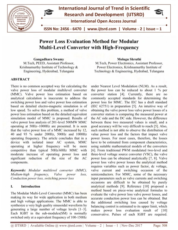
There is no common accepted way for calculating the valve power loss of modular multilevel converter MMC . Valve power loss estimation based on analytical calculation is inaccurate to address the switching power loss and valve power loss estimation based on detailed electro magnetic simulation is of low speed. To solve this problem, a method of valve power loss estimation based on the detailed equivalent simulation model of MMC is proposed. Results of valve power loss analysis of 201 level 500MW MMC operating at 50Hz~1000Hz are presented. It is seen that the valve power loss of a MMC increased by 12, 40 and 93 under 200Hz, 500Hz and 1000Hz operating frequency. The article concludes that in a device with isolated inner AC system, MMC operating at higher frequency will be more competitive than typical 50Hz 60Hz MMC with moderate increase of operating power loss and significant reduction of the size of the AC components. Gangadhara Swamy | Molugu Shruthi "Power Loss Evaluation Method for Modular Multi-Level Converter with High-Frequency" Published in International Journal of Trend in Scientific Research and Development (ijtsrd), ISSN: 2456-6470, Volume-2 | Issue-1 , December 2017, URL: https://www.ijtsrd.com/papers/ijtsrd7027.pdf Paper URL: http://www.ijtsrd.com/engineering/electrical-engineering/7027/power-loss-evaluation-method-for-modular-multi-level-converter-with-high-frequency/gangadhara-swamy<br>

E N D
International Research Research and Development (IJTSRD) International Open Access Journal International Open Access Journal International Journal of Trend in Scientific Scientific (IJTSRD) ISSN No: 2456 - 6470 | www.ijtsrd.com | Volume Loss Evaluation Method for Modular ISSN No: 2456 | www.ijtsrd.com | Volume - 2 | Issue – 1 Power Loss Evaluation Method f Multi-Level Converter Level Converter with High-Frequency or Modular Frequency Gangadhara Swamy M.Tech, PEED, Assistant Professor, Krishnamurthy Institute of Technology & Engineering, Hyderabad, Telangana ABSTRACT Molugu Shruthi Molugu Shruthi Electronics, Assistant Professor, Power Electronics, Krishnamurthy Institute of Technology & Engineering, Hydrabad, Telangana M.Tech, PEED, Assistant Professor, Krishnamurthy Institute of Technology & Engineering, Hyderabad, Telangana M.Tech, Power Electronics, Assistant Professor, Power Electronics, Krishnamurthy Institute of Technology & Engineering, Hydrabad, Telangana There is no common accepted way for calculating the valve power loss of modular multilevel converter (MMC). Valve power loss estimation based on analytical calculation is inaccurate to address the switching power loss and valve power loss estimation based on detailed electro-magnetic simulation is of low speed. To solve this problem, a method of valve power loss estimation based on the detailed equivalent simulation model of MMC is proposed. Results of valve power loss analysis of 201-level 500MW MMC operating at 50Hz~1000Hz are presented. It is seen that the valve power loss of a MMC increased by 12, 40 and 93 % under 200Hz, 500Hz and 1000Hz operating frequency. The article concludes that in a device with isolated inner AC system, MMC operating at higher frequency will be more competitive than typical 50Hz/60Hz MMC with moderate increase of operating power loss and significant reduction of the size of the AC components. Keywords: Modular multilevel converter (MMC), Medium-high frequency, Conduction power loss, switching power loss I. Introduction There is no common accepted way for calculating the under Nearest Level Modulation (NLM). As a result, the power loss can be reduced to about 1 % per converter station [4]. Currently, there are no epted standards for determining the power loss for MMC. The IEC has a draft standard (IEC 62751) in preparation [5]. An intuitive way of obtaining the valve power loss valve power losses of a converter station is comparing the measured power at and the DC side. However, the difference between these two measured values is small, and a good accuracy will be very difficult to reach [5]. Also, such method is not able to observe the distribution of value power loss and the factors that impact valve ower losses. For most cases, therefore, the losses have to be estimated from component characteristics, using suitable mathematical models of the converters [6]. From traditional PWM modulated two-level and level voltage source converter (VSC), the valve obtained analytically [7, 8]. Valve power loss valve power losses the analytical method requires variables such as power factor, dc voltage, valve current and switching occasion of the semiconductors. For MMC, some of the necessary nput parameters such as valve currents and switching occasions are difficult to be obtained by purely analytical methods [9]. Reference [10] proposed a wise analytical formulas to evaluate the valve power loss valve power losses, and accurate conduction power loss can be obtained. But the additional switching loss caused by voltage balancing control is estimated to its upper limit, which makes power loss evaluation result of [10] under Nearest Level Modulation (NLM). As a result, the power loss can be reduced to about 1 % per converter station [4]. Currently, there are no commonly accepted standards for determining the power loss for MMC. The IEC has a draft standard (IEC 62751) in preparation [5]. An intuitive obtaining the valve power loss valve power losses of a converter station is comparing the measured power at the AC side and the DC side. However, the difference between these two measured values is small, and a good accuracy will be very difficult to reach [5]. Also, such method is not able to observe the distribution of value power loss and the factors that impact valve power losses. For most cases, therefore, the losses have to be estimated from component characteristics, using suitable mathematical models of the converters [6]. From traditional PWM modulated two three-level voltage source converter (VSC), the v power loss can be obtained analytically [7, 8]. Valve power loss valve power losses the analytical method requires variables such as power factor, dc voltage, valve current and switching occasion of the semiconductors. For MMC, some of the necessary input parameters such as valve currents and switching occasions are difficult to be obtained by purely analytical methods [9]. Reference [10] proposed a method based on piece-wise analytical formulas to evaluate the valve power loss valve power losses, and accurate conduction power loss can be obtained. But the additional switching loss caused by voltage balancing control is estimated to its upper limit, which makes power loss evaluation result of [10] conservative. Pulses of each IGBT are required. conservative. Pulses of each IGBT are required. multilevel converter (MMC). Valve power loss estimation based on analytical calculation is inaccurate to address the switching power loss and valve power loss estimation magnetic simulation is of a method of valve power loss estimation based on the detailed equivalent simulation model of MMC is proposed. Results of level 500MW MMC operating at 50Hz~1000Hz are presented. It is seen increased by 12, 40 and 93 % under 200Hz, 500Hz and 1000Hz operating frequency. The article concludes that in a device with isolated inner AC system, MMC operating at higher frequency will be more competitive than typical 50Hz/60Hz MMC with se of operating power loss and significant reduction of the size of the AC Modular multilevel converter (MMC), high frequency, Conduction power loss, switching power loss Valve Valve power power loss, loss, The Modular Multi-Level Converter (MMC) has been making its way for wide application in both medium and high voltage applications. The MMC is able to synthesize a very high quality sinusoidal waveform by generating a large number of voltage levels [1 Each IGBT in the sub-modules(SM) is normally switched only at a equivalent frequency of 100 switched only at a equivalent frequency of 100-150Hz Level Converter (MMC) has been making its way for wide application in both medium and high voltage applications. The MMC is able to synthesize a very high quality sinusoidal waveform by generating a large number of voltage levels [1–3]. modules(SM) is normally @ IJTSRD | Available Online @ www.ijtsrd.com @ IJTSRD | Available Online @ www.ijtsrd.com | Volume – 2 | Issue – 1 | Nov-Dec 2017 Dec 2017 Page: 508
International Journal of Trend in Scientific Research and Development (IJTSRD) ISSN: 2456-6470 Electro-magnetic recommended to obtain these variables. Reference [9] proposed interpolating equations to calculate voltage and currents during the switching event so as to accurately represent the switching power losses. But such integrable equations are difficult to realize in simulation tools. By analyzing the simulated voltage and current waveforms, power losses are evaluated with different converter operation points in [8], where the detailed electro-magnetic simulation model of MMC was applied. The method of is accurate, except that it is based on detailed switching model of MMC and therefore the valve power loss estimation requires significant of simulation time. It may take one week to simulate 5-seconds dynamics of a 401-level MMC. Therefore, the valve power loss evaluation based on detailed switching model is time consuming and inconvenient to analyze the impacts affecting valve power loss of MMC, which typically involves repeatedly simulation. To solve such challenges, a valve power loss evaluation method based on fast MMC simulation model is proposed in this paper. simulations are therefore analytically integrable In eq.(1), Δt is the integration step, UCi(t) is the voltage of SM capacitor, UCi(t − Δt) is the SM voltage in previous integration, SCi is a signal function with values of 1 and 0, which represents switch-on state and bypass state of SM, ISMi is the arm current flowing into SM. By trapezoid integral: I armA is the upper arm current of phase A and it is the same of ISMi. The output voltage of number ith SM is: Uconi is the on-state voltage of an IGBT or diode, it exhibits when device is in the conducting state. The onstate voltage depends on its current in a non-linear manner and it is usually represented as a piecewise- linear approximation with a threshold voltage U0 and a slope resistance Rcon, as shown by equation (4): II. Method Average value model for power loss study Basic operating principles of mmc Figure 1 (a) shows a three-phase MMC consisting of an upper arm and a lower arm for each phase unit, each arm has N half- bridge sub-modules (denoted as SM1-SMN) and one inductor L in series. The topology and control method of MMC has been well studied in. To calculate valve power loss accurately, firing pulses for T1, T2, arm current and SM capacitor voltage are required from electro-magnetic simulation results. But, as pointed out in , detailed switch model of MMC costs excessively long simulation time. Thus, a fast simulation model of MMC is proposed as a substitution to obtain the above variables for valve power loss. Figure 1 (b) shows schematic of the fast MMC simulation model (taking one phase as an example). In this model, each arm is represented by a controlled voltage source with the magnitude of Uarm. The user defined component ‘Calculate SM Voltages’ takes arm current Iarm and firing pulse SC(1:N) of each SM as the inputs to get capacitor voltage for each SM. The ‘Modulation and Voltage Balancing Control’ module takes reference voltage Uref, arm current Iarm and capacitor voltage UC(1:N) as inputs to generate the firing pulses of each sub module . The voltage of SM can be expressed as: @ IJTSRD | Available Online @ www.ijtsrd.com | Volume – 2 | Issue – 1 | Nov-Dec 2017 Page: 509
International Journal of Trend in Scientific Research and Development (IJTSRD) ISSN: 2456-6470 Junction temperature and parameters adjustment the valve power loss requires the parameters such as the threshold voltage, conduction switching energy of the power semiconductors. These parameters are related to the PN junction temperature of power semiconductors. In return, PN junction temperature also depends on the heat generated by loss power. Thus, to accurately estimate valve power loss, power loss and junction temperature of each device need to be calculated iteratively. Since the junction temperature cannot be measured directly, it will be estimated using a thermal circuit as presented in literatures [9] and Input for the thermal circuit is the measured temperature of the heat sink while output is the estimated PN junction temperature. Procedure of iterating the PN junction temperature can be described as follows: 1)The heat sink temperature will be measured and an initial value of PN junction temperature is given; 2)Based on the present PN junction temperature, parameters such as the threshold voltages, conduction resistance and switching energy will be calculated from the datasheet provided by the 3)manufacture; 4)From the obtained parameters of step 2) and the simulated arm currents, sub-module capacitor voltages and the switching state of each sub- module, valve power loss of the power semiconductor will be estimated; 5)Based on the estimated valve power loss, the measured heat sink temperature and the thermal circuit of the power semiconductor, a new estimated PN junction temperature is obtained; Substitute the obtained new PN junction temperature of step 4) into step 2) and repeat step 2) to 4) until the difference between the previous estimated PN junction temperature and the present estimated PN junction temperature falls within a pre-defined deviation. calculation method based on fast simulation model Categories of valve power losses The power losses are usually estimated from component characteristics, using models of the converters. The valve power loss can be subdivided into 5 iterms: 1)IGBT conduction losses; 2)Diode conduction losses; 3)IGBT switching losses; 4)Diode recovery losses; 5)IGBT and diode cut-off losses. The formulas for each item of valve power loss has been well Analysis shows that compared with 50Hz operation, the valve power loss of MMC increased by 12, 40 and 93 % under 200Hz, 500Hz and 1000Hz. Since the volume of arm inductor, SM capacitor and transformer of an MMC can be reduced inversely proportional to the operating frequency. Thus, MMC operating at higher frequency will be more competitive than typically 50/ 60Hz MMC for potential applications in offshore frontto- front connected dc-dc converters. III. Flow chart of valve power loss resistance and A common valve power loss program for MMC is designed in this paper. Flowchart of the program is shown in Fig. 2. It is based on Matlab/GUI with interface to PSCAD/EMTDC. Firstly, simulation results of fast model in PSCAD are saved as. OUT file. Then the data of capacitor voltages (Uc), arm current (Iarm) and switching states of each submodules( SC) of the six arms will be read by the ‘Valve CONCLUSION IV. A fast electro-magnetic simulation model of MMC is developed for accurate power loss. It can obtain almost identical simulation results as the detailed switch model while simulation speed can be improved by approximately 10,000 times. A more accurate program for estimating valve power loss of MMC and junction temperature of devices is proposed, by linking PSCAD/EMTDC and Matlab. The accuracy of power loss calculation is verified by comparison with detailed model of MMC. Relationships between power losses, the power transfer level and operating frequencies are presented and fitted, with a case of 201-level MMC working at 50Hz ~ 1000Hz. Valve power loss suitable mathematical @ IJTSRD | Available Online @ www.ijtsrd.com | Volume – 2 | Issue – 1 | Nov-Dec 2017 Page: 510
International Journal of Trend in Scientific Research and Development (IJTSRD) ISSN: 2456-6470 REFERENCES 1.Dorn, J., Huang, H., & Retzmann, D. (2007). Novel voltage-sourced converters for HVDC and FACTS applications (pp. 1–6). Osaka: CIGRE Symposium. Applications (EPE 2011), Proceedings of the 2011-14th European Conference on, Birmingham, 2011, pp. 1–10. 7.Pang, H, Tang, G, He, Z. ‘‘Evaluation of losses in VSC-HVDC transmission system,’’ Power and Energy Society General Meeting-Conversion and Delivery of Electrical Energy in the 21st Century, 2008 IEEE, Pittsburgh, PA, 2008, pp. 1–6. 2.Dorn, J., Huang, H., & Retzmann, D. (2008). A new multilevel voltage topology for HVDC applications (pp. 1–8). Paris, France: Proc. CIGRE. sourced converter 8.Zhang, Y, Adam, GP, Lim, TC, Finney, SJ, Williams, B.W. ‘‘Voltage source converter in high voltage applications: Multilevel versus two-level converters,’’ AC and DC Power Transmission, 2010. ACDC. 9th IET International Conference on, London, 2010, pp. 1–5. 3.Deore, S. R., Darji, P. B., & Kulkarni, A. M. (2013). Switching function analysis of half- and full-bridge modular multi-level converters for HVDC applications. Transmission & Distribution, 7(11), 1344–1356. IET Generation, 4.Jones, PS, Davidson, CC. ‘‘Calculation of power losses for MMC-based VSC HVDC stations,” Power Electronics and Applications (EPE), 2013 15th European Conference on, Lille, 2013, pp. 1– 10. 9.Zygmanowski, M, Grzesik, B, Fulczyk M, Nalepa, R. ‘‘Analytical and numerical power loss analysis in Modular Multilevel Converter,’’ Industrial Electronics Society, IECON 2013 - 39th Annual Conference of the IEEE, Vienna, 2013, pp. 465– 470. 5.IEC 62751: ‘Determination of power losses in voltage sourced converter (VSC) valves for high- voltage direct current (HVDC) systems’. 2013. 10.Zhang, Z., Xu, Z., & Xue, Y. (2014). Valve power lossValve power losses Evaluation Based on Piecewise Analytical Method for MMC–HVDC Links. IEEE Transactions on Power Delivery, 29, 1354–1362 6.Oates, C, Davidson, C. ‘‘A comparison of two methods of estimating losses in the Modular Multi-Level Converter,’’ Power Electronics and @ IJTSRD | Available Online @ www.ijtsrd.com | Volume – 2 | Issue – 1 | Nov-Dec 2017 Page: 511