Download
1 / 8
80 likes | 97 Views
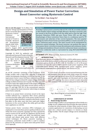
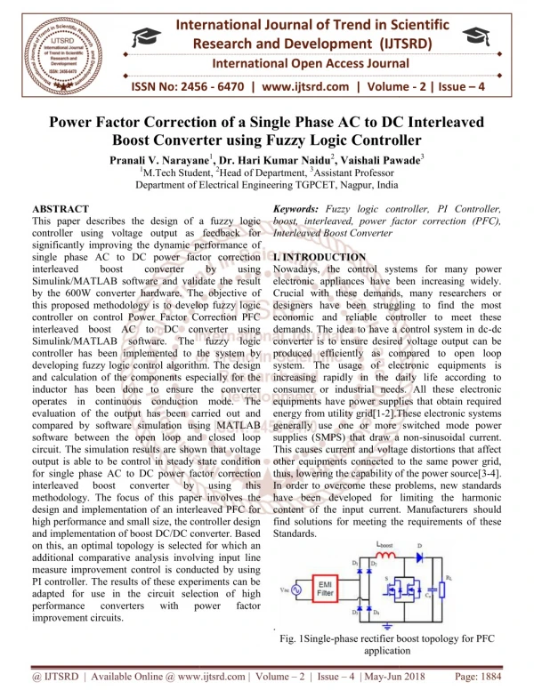
This paper describes the design of a fuzzy logic controller using voltage output as feedback for significantly improving the dynamic performance of single phase AC to DC power factor correction interleaved boost converter by using Simulink MATLAB software and validate the result by the 600W converter hardware. The objective of this proposed methodology is to develop fuzzy logic controller on control Power Factor Correction PFC interleaved boost AC to DC converter using Simulink MATLAB software. The fuzzy logic controller has been implemented to the system by developing fuzzy logic control algorithm. The design and calculation of the components especially for the inductor has been done to ensure the converter operates in continuous conduction mode. The evaluation of the output has been carried out and compared by software simulation using MATLAB software between the open loop and closed loop circuit. The simulation results are shown that voltage output is able to be control in steady state condition for single phase AC to DC power factor correction interleaved boost converter by using this methodology. The focus of this paper involves the design and implementation of an interleaved PFC for high performance and small size, the controller design and implementation of boost DC DC converter. Based on this, an optimal topology is selected for which an additional comparative analysis involving input line measure improvement control is conducted by using PI controller. The results of these experiments can be adapted for use in the circuit selection of high performance converters with power factor improvement circuits. Pranali V. Narayane | Dr. Hari Kumar Naidu | Vaishali Pawade "Power Factor Correction of a Single Phase AC to DC Interleaved Boost Converter using Fuzzy Logic Controller" Published in International Journal of Trend in Scientific Research and Development (ijtsrd), ISSN: 2456-6470, Volume-2 | Issue-4 , June 2018, URL: https://www.ijtsrd.com/papers/ijtsrd14459.pdf Paper URL: http://www.ijtsrd.com/engineering/electrical-engineering/14459/power-factor-correction-of-a-single-phase-ac-to-dc-interleaved-boost-converter-using-fuzzy-logic-controller/pranali-v-narayane<br>

E N D
International Research Research and Development (IJTSRD) International Open Access Journal Power Factor Correction of a Single Phase AC to DC Interleaved Boost Converter using Fuzzy Logic Controller Pranali V. Narayane1, Dr. Hari Kumar Naidu2, Vaishali Pawade M.Tech Student, 2Head of Department, 3Assistant Professor Department of Electrical Engineering TGPCET, Nagpur, India International Journal of Trend in Scientific Scientific (IJTSRD) International Open Access Journal ISSN No: 2456 ISSN No: 2456 - 6470 | www.ijtsrd.com | Volume 6470 | www.ijtsrd.com | Volume - 2 | Issue – 4 Power Factor Correction of a Single Phase AC to DC Interleaved Boost Converter using Fuzzy Logic Controller Power Factor Correction of a Single Phase AC to DC Interleaved Boost Converter using Fuzzy Logic Controller Pranali V. Narayane 1M.Tech Student Department of Electrical Engineering Vaishali Pawade3 Keywords:Fuzzy logic controller, PI Controller, boost, interleaved, power factor correction (PFC), Interleaved Boost Converter I. INTRODUCTION Nowadays, the control systems for many electronic appliances have been increasing widely. Crucial with these demands, many researchers or designers have been struggling to find the most economic and reliable controller to meet these demands. The idea to have a control system in dc converter is to ensure desired voltage output can be produced efficiently as compared to open loop system. The usage of electronic equipments is increasing rapidly in the daily life according to consumer or industrial needs. All these electronic equipments have power supplies that obtain required energy from utility grid[1-2].These electronic systems generally use one or more switched mode power supplies (SMPS) that draw a non This causes current and voltage distortions that affect other equipments connected to the same power grid, thus, lowering the capability of the power source In order to overcome these problems, new standards have been developed for limiting the harmonic content of the input current. Manufacturers should find solutions for meeting the requirements of these Standards. ABSTRACT This paper describes the design of a controller using voltage output as feedback for significantly improving the dynamic performance of single phase AC to DC power factor correction interleaved boost converter Simulink/MATLAB software and validate the result by the 600W converter hardware. The objective of this proposed methodology is to develop fuzzy logic controller on control Power Factor Correction PFC interleaved boost AC to DC converter using Simulink/MATLAB software. The fuzzy logic controller has been implemented to the system by developing fuzzy logic control algorithm. The design and calculation of the components especially for the inductor has been done to ensure the converter operates in continuous conduction mode. The evaluation of the output has been carried o compared by software simulation using MATLAB software between the open loop and closed loop circuit. The simulation results are shown that voltage output is able to be control in steady state condition for single phase AC to DC power factor correcti interleaved boost converter methodology. The focus of this paper involves the design and implementation of an interleaved PFC for high performance and small size, the controller design and implementation of boost DC/DC converter. Based on this, an optimal topology is selected for which an additional comparative analysis involving input line measure improvement control is conducted by using PI controller. The results of these experiments can be adapted for use in the circuit selection of hig performance converters improvement circuits. Fuzzy logic controller, PI Controller, boost, interleaved, power factor correction (PFC), This paper describes the design of a fuzzy logic controller using voltage output as feedback for significantly improving the dynamic performance of single phase AC to DC power factor correction interleaved boost converter Simulink/MATLAB software and validate the result onverter hardware. The objective of this proposed methodology is to develop fuzzy logic controller on control Power Factor Correction PFC interleaved boost AC to DC converter using Simulink/MATLAB software. The fuzzy logic by by using using Nowadays, the control systems for many power electronic appliances have been increasing widely. Crucial with these demands, many researchers or designers have been struggling to find the most economic and reliable controller to meet these demands. The idea to have a control system in dc-dc erter is to ensure desired voltage output can be produced efficiently as compared to open loop The usage of electronic equipments is increasing rapidly in the daily life according to consumer or industrial needs. All these electronic e power supplies that obtain required 2].These electronic systems generally use one or more switched mode power supplies (SMPS) that draw a non-sinusoidal current. This causes current and voltage distortions that affect ipments connected to the same power grid, thus, lowering the capability of the power source[3-4]. In order to overcome these problems, new standards have been developed for limiting the harmonic content of the input current. Manufacturers should ions for meeting the requirements of these o the system by developing fuzzy logic control algorithm. The design and calculation of the components especially for the inductor has been done to ensure the converter operates in continuous conduction mode. The evaluation of the output has been carried out and compared by software simulation using MATLAB software between the open loop and closed loop circuit. The simulation results are shown that voltage output is able to be control in steady state condition for single phase AC to DC power factor correction interleaved boost converter methodology. The focus of this paper involves the design and implementation of an interleaved PFC for high performance and small size, the controller design and implementation of boost DC/DC converter. Based this, an optimal topology is selected for which an additional comparative analysis involving input line measure improvement control is conducted by using PI controller. The results of these experiments can be adapted for use in the circuit selection of high performance converters by by using using this this with with power power factor factor . Fig. 1Single-phase rectifier boost topology for PFC application application phase rectifier boost topology for PFC @ IJTSRD | Available Online @ www.ijtsrd.com @ IJTSRD | Available Online @ www.ijtsrd.com | Volume – 2 | Issue – 4 | May-Jun 2018 Jun 2018 Page: 1884
International Journal of Trend in Scientific Research and Development (IJTSRD) ISSN: 2456-6470 In the general usage, different load groups are supplied by different phases. If one of the phases is loaded with nonlinear loads, unbalanced currents flow through the neutral line of star configuration. These unbalanced currents cause heating and power loss in the conductors and voltage electromagnetic compatibility (EMC) problems occur. Moreover the harmonic content of this pulsating current causes additional losses and dielectric stresses in capacitors and cables, increasing currents in windings of rotating machinery and transformers and noise emissions in many products, and bringing about early failure of fuses and other safety components. Harmonics can affect other devices that are connected to the same system. DC-DC converters are non-linear in nature hence the design of controller is most challenging task for DC- DC converters. The general control principle for power electronic converter is shown in figure 2. Conventionally, PI, PD and PID controller are most popular controllers and widely used in most power electronic closed loop appliances however recently there are many researchers reported successfully adopted Fuzzy Logic Controller (FLC) to become one of intelligent controllers to their appliances [3]. With respect to their successful implementation, control closed loop boost converter and opened loop boost converter will compare the efficiency of the converters. methodology implemented in this paper is using fuzzy logic controller with feed back by introduction of voltage output respectively. The introduction of voltage output in the circuit will be fed to fuzzy controller to give appropriate measure on steady state signal. The fuzzy logic controller serves as intelligent controller for this propose. This Methodology can be easily applied to many dc-dc converter topologies such as Buck, Boost and Buck-Boost. The power sources have quite low –voltage output and requires series connection of voltage booster to provide higher output voltage. DC-DC Boost converter is generally used to further boost the voltage to the required level [6]. Other booster converter such as Boost, Buck, Boost series resonant full bridge and push-pull are not recommended due to objectionable ripples in the current flowing out of the renewable energy sources [7]. During electronically extreme thermal excursions it become to develop a high temperature, high power density and high efficiency electrical power system which can be reliably function. To fulfill this requirement interleaved boost converters have been studies in recent years due to their potential to improve power converter performance in terms of efficiency, size, conducted electromagnetic emission and transient response [6]. The power system can have high voltage step up and smaller ripple at the output voltage and output current. Interleaved boost converter has low switching loss and faster transient response [7]. distortion and methodology This kind of Fig.2. General control principle for a power electronic converter There are linear and non-linear controllers. Non-linear controllers are more accurate as compared to linear controller [3]. Intraditional controller, application of linear control theory based on linearised model. A linear control method fails to respond properly to any variation in the operating point and load disturbance. To overcome these issues, nonlinear controllers can be used which are more robust and have faster dynamic response [4]. There are many non-linear control schemes, such as fuzzy logic control, current- mode control and PI control proposed for DC-DC converter. Due to simple implementation PI control and fuzzy logic control can be applied with satisfactory results [4]. Out of this controller PI control is powerful method which able to makes the system very robust. The system with PI control avoided effects of modeling uncertainties, fluctuations and disturbance of parameter and load variations. The advantages of PI controller are robustness and stability [4]. Due to this reason PI control technique has gained popularity in the applications involving converter and inverters [5]. and model free The objective of this paper is the practical implementation of Fuzzy Logic controller of single phase AC-DC interleaved boost converter. Simulation results are given in order to show the effectiveness of the Fuzzy logic control. @ IJTSRD | Available Online @ www.ijtsrd.com | Volume – 2 | Issue – 4 | May-Jun 2018 Page: 1885
International Journal of Trend in Scientific Research and Development (IJTSRD) ISSN: 2456-6470 which reduces the dc- output capacitor ripple Ioutas a function of duty cycle The design aspects of Interleaved Boost Converter are given in the below section: II. DC TO DC BOOST CONVETER A.Boost Ratio The boosting ratio of the converter is a function of the duty ratio. It is same as in conventional boost converter. It is defined as Vdc/Vin= 1/1-D Where Vdc is the output voltage, Vin is the input voltage and D is the duty ratio. Fig.3. DC-DC Boost Converter Fig. 3 shows a DC–DC boost converter. It consists of a DC input voltage source (Vin), a controlled switch (Sw), a diode (D), a filter inductor (L), a filter capacitor (C), and a load resistor (R). The equations describing the operation of the converter can be written for the switching conditions ON and OFF, respectively as B.Input Current The input current can be calculated by the input power and the input voltage. Iin = Pin/Vin Where Pin is the input power, in is the input voltage C.Inductor current ripple peak –to-peak amplitude The inductor current ripple peak-to-peak amplitude is given by. I L1, L2, L3=VinD/fswL Where fsw is the switching frequency, D is the duty cycle, Vin is the input voltage and L is the inductance. Interleaved boost converter is employed to reduce input and output a voltage ripple which reduces the size of filters since the output current splitted into N parts it reduces the I2R losses and inductor loss which leads to higher efficiency [6]. IV. FUZZY LOGIC CONTROL L. A. Zadeh presented the first paper on fuzzy set theory in 1965. Since then, a new language was developed to describe the fuzzy properties of reality, which are very difficult and sometime even impossible to be described using conventional methods. Fuzzy set theory has been widely used in the control area with some application to dc-to-dc converter system. A simple fuzzy logic control is built up by a group of rules based on the human knowledge of system behaviour. Matlab/Simulinksimulation model is built to study the dynamic behaviour of dc- to-dc converter and performance of proposed controllers. Furthermore, design of fuzzy logic controller can provide desirable both small signal an dlarge signal dynamic performance at same time, which is not possible with linear control technique. Thus, fuzzy logic controller has been potential ability to improve the robustness of dc-to-dc converters. The basic scheme of a fuzzy logic controller is shown in figure 2 and consists of four principal components such as: a fuzzyficationinterface, which converts input data into suitable linguistic values; a knowledge base, Where ‘u’ is the control input which takes 1 for the ON state of the switch and 0 for the OFF state. III. INTERLEAVED BOOST CONVERTER Interleaved boost converter can be simply obtained by operating three boost converters operating 1200out of phase. The input current is the sum of three inductor currents IL1, IL2 and IL3. Because the inductor ripple current is out of phase, they cancel each other and reduce the input ripple current produce by inductor of boost converter. Fig.4 interleaved boost converter topology The output capacitor current is the sum of the three diode currents, I1+I2+I3 minus Dc output current, @ IJTSRD | Available Online @ www.ijtsrd.com | Volume – 2 | Issue – 4 | May-Jun 2018 Page: 1886
International Journal of Trend in Scientific Research and Development (IJTSRD) ISSN: 2456-6470 which consists of a data base with the necessary linguistic definitions and the control rule set; a decision-making logic which, simulating a human decision process, infer the fuzzy control action from the knowledge of the control rules and linguistic variable definitions; a defuzzificationinterface which yields non fuzzy control action from an inferred fuzzy control action [4]. C.Fuzzy Logic Membership Function The of single phase AC-DC interleaved boost converter is a nonlinear function of the duty cycle because of the small signal model and its control method was applied to the control of boost converters. Fuzzy controllers do mathematical model. Instead, they are designed based on general knowledge of the plant. Fuzzy controllers are designed to adapt to varying operating points. Fuzzy Logic Controller is designed to control the output of boost dc-dc converter using Mamdani style fuzzy inference system. Two input variables, error (e) and change of error (de) are used in this fuzzy logic system. The single output variable (u) is duty cycle of PWM output [7]. not require an exact Fig,5 General fuzzy logic controller The objective is to steer the time varying load voltage y to a reference value y(t). According to strategy we define two PI surface. A.Fuzzy logic controller on the single phase AC to DC PFC Interleaved Boost converter An analysis of single phase AC-DC interleaved boost converter circuit revealed that the inductor current plays significant task in dynamic response of boost converter. Additionally, it can provide the storage energy information in the converter. Thus, any changes on the inductor current may affect output voltage and output voltage will provide steady state condition information of converter. However, the three main parameters need to be considered when designingboost converters are power switch, inductor and capacitor. In this objective to achieve the desired output voltage and the stability is by designing the power switch [6]. B. Analytical Expressions There are few types of power switches in order to develop the design. The common power switches are BJT, power MOSFET, IGBT etc. Since the characteristics of the MOSFET are fast switching and voltage driven, they have been chosen for the power switching in this designing requirement. In this case, the parameters value of design requirement for the single phase AC to DC PFC Interleaved Boost converter is been set. The value of the parameter can be determined as illustrated in Table I below: Fig.6: The Membership Function plots of error. Fig 7: The Membership Function plots of change error. Fig:8The Membership Function plots of duty ratio. D.Fuzzy Logic Table Rules The objective of this paper is to control the output voltage of the boost converter. The error and change of error of the output voltage will be the inputs of fuzzy logic controller. These 2 inputs are divided into five groups; NB: Negative Big, NS: Negative Small, ZO: Zero Area, PS: Positive small and PB: Positive Big an dits parameter [8][9][10]. These fuzzy control TABLE I. SIMULATION MODEL PARAMETERS @ IJTSRD | Available Online @ www.ijtsrd.com | Volume – 2 | Issue – 4 | May-Jun 2018 Page: 1887
International Journal of Trend in Scientific Research and Development (IJTSRD) ISSN: 2456-6470 rules for error and change of error can be referred in the table that is shown in Table II as per below: Fig. 6 shows waveform of output current of interleaved boost converter. Fig. 12. Simulation waveform of output power Fig. 7 shows waveform of output power of interleaved boost converter. TABLE II. SIMULATION MODEL PARAMETERS V. SIMULATION RESULTS The single phase AC to DC PFC Interleaved Boost converter parameters used in simulation are given in table II. The simulation of the interleaved PFC boost converter is carry out in the simulink/MATLAB. The reliability of the converter is checked by varying the magnitude of the input voltage. At the constant load the input current is change for the variation in the input voltage. The parameter of the converter is given in Table II. Fig. 13. Simulation waveform of output voltage for change in input voltage Fig. 8 shows waveform of output voltage which remains unchanged as input voltage change of interleaved dc-dc boost converter. Fig.9. Simulation waveform of input voltage Fig. 4 shows waveform of single phase ac input voltage which is applied to rectifier. Fig.14. Simulation waveform of output voltage for change in input voltage Fig. 9 shows clearly as change input voltage output voltage does not change for same resistive load. TABLE II. OUTPUT VOLTAGE AT DIFFERENT INPUT VOLTAGE Fig. 10. Simulation waveform of output voltage Fig. 5 shows waveform of output voltage of interleaved boost converter. As change in the input voltage occurred due to due any uncertainty the output unchanged. Output voltage remains stable which is clearly shown by simulation waveform and the values shown in Table. II voltage remains Fig.11. Simulation waveform of output current @ IJTSRD | Available Online @ www.ijtsrd.com | Volume – 2 | Issue – 4 | May-Jun 2018 Page: 1888
International Journal of Trend in Scientific Research and Development (IJTSRD) ISSN: 2456-6470 TABLE IV. OUTPUT VOLTAGE AT DIFFERENT LOAD the some harmonics is present in the input of the 50Hz power supply. The result is varying due to the above reasons. Moreover, it does not require the line voltage sensing, the multiplier, and the current loop compensation design owing to its beneficial characteristics in nature, which greatly simplifies control circuitry. The intrinsic features of the proposed method enable a current balancing between the interleaved modules by just letting them use the phase-shifted modulated carrier signals with the same amplitude. The operation principle has been presented and mathematically detailed. As per values shown in table III it is cleared that variations in the load parameters or any uncertainty output voltage remains same. As per values shown in table III it is cleared that variations in the load parameters or any uncertainty output voltage remains stable. For same value of input voltage with different load resistance output voltage remains stable which is clearly observed and shown in simulation waveform. From above explanation it is clear that fuzzy logic control is robust and stable which proves the advantages of fuzzy logic control. VI. EXPERIMENTAL SETUP Fig. 16. Pulse generated in hardware TABLE IV. OUTPUT VOLTAGE AT DIFFERENT INPUT VOLTAGE Fig. 14. Experimental setup of a PI control dc-dc interleaved boost converter VII. EXPERIMENTAL RESULTS The performance of the fuzzy logic controller is experimentally verified. The specification of the converter is the same as that used in simulation. The experimental results match the simulation very well. Also, it can be seen that the output voltage is a little less than or higher than the desired 650V in each circumstance, due to the parasitic parameters in the hardware circuit, which are neglected in simulation. From above table output voltage for various input voltage values is given which is more or less than 650V due to the parasitic parameters in the hardware circuit. VIII. CONCLUSIONS Design of a Fuzzy Logic controller on control boost DC/DC converter by using MATLAB has been successfully achieved. A simple algorithm based on the prediction of Fuzzy Logic controller, possibly using the Fuzzy rules parameter, is showing to be more convenient than the circuit without fuzzy. As the 230 V input on the output voltage for the closed loop circuit (with fuzzy logic controller) with 0% Fig. 15. Hardware Input voltage waveform Simulation result and the hardware result are differ from each other as it is clearly seen from above result @ IJTSRD | Available Online @ www.ijtsrd.com | Volume – 2 | Issue – 4 | May-Jun 2018 Page: 1889
International Journal of Trend in Scientific Research and Development (IJTSRD) ISSN: 2456-6470 overshoot shows the better performance compared to the open loop circuit (without fuzzy logic controller) whereby it has 80% overshoot. Moreover, the value of the output current also improving corresponding to the system and produce a constant value for the output current as 0.5 A. This scenario would not happen to the output current of the open loop circuit. Using a closed loop circuit with fuzzy logic controller, it is confirmed that the single phase AC-DC interleaved boost converter gives a value of output voltage exactly as circuit requirement. Hence, the closed loop circuit of single phase AC-DC interleaved boost converter controlled that by Fuzzy Logic controller confirmed the methodology and requirement of the proposed approach. These studies could solve many types of problems regardless on stability because it is evidence that fuzzy logic controller is an intelligent controller to their appliances. This paper presented a PI controller of DC-DC interleaved boost converter. The various conditions are considered for testing the simulation results. After variation in the input voltage output voltage remains constant. Simultaneously by changing the resistive load in the system of simulation model does not effect on the output voltage. on Volume 17,vIssue 5, Sept. 2002 Page(s):658 – 668. 4.Guang Feng, Wanfeng Zhang, Yan-Fei Liu. “An adaptive current mode fuzzy logic controller for dcto-dc converters”.Applied Power Electronics Conference and Exposition, 2003. APEC '03. Eighteenth Annual IEEE Volume 2, 9-13 Feb. 2003 Page(s):983 - 989 vol.2 5.Mattavelli, P., Rossetto, L., Spiazzi, G., Tenti, P. “General-purpose fuzzy controller for dc/dc converters”.Applied Conference and Exposition, 1995. APEC '95. ConferenceProceedings 1995., Tenth Annual Issue 0, Part 2, 5-9 March 1995 Page(s):723 – 730 vol.2 Power Electronics 6.Yan-Fei Liu, P. C. Sen. “Digital control of switching power converters”. Proceedings of the 2005, IEEE Conference on Control Applications, Toronto, Canada, august 28-31, 2005. 7.W. C., & Tse, C. K. (1996). “Development of a fuzzy logic controller for DC/DC converters: Design, computer simulation, and experimental evaluation”. IEEE Transactions on Power Electronics. 8.W. C., Tse, C. K., & Lee, Y. S. (1994). “A fuzzy logic controller for DC–DC converter”. In IEEE power electronics specialists conference records. Hardware results also shows the same expected results. Slight variations in the output voltage observed at the time of hardware experimentation. The simulation and hardware result shows that Fuzzy logic control is most robust and stable. This method which is proposed in this paper further may be investigated in other topologies of converters. REFERENCES 1.Hari Priya T., Alivela M. Parimi, U.M. Rao,“Development of Hybrid Controller for Photovoltaic Based DC-DC Boost Converter in DC Grid Connected Applications,”International Conference on Circuit, Power and Computing Technologies, 2016. 9.] V. S. C. Raviraj, P. C. Sen, “Comparative Study of Proportional- Integral, Sliding mode, and Fuzzy Logic Controllers for Power Converters”. IEEE Trans on Industry Applications, Vol. 33, No. 2,March/April 1997. 10.K. Viswanathan, D. Srinivasan and R. Oruganti, “A Universal Fuzzy Controller for a Non-linear Power Electronic Converter”. IEEE International Conference on Fuzzy Systems, 2002, Vol. 1 11.Carolina Evangelista, Alessandro Pisano, Paul Puleston, Elio Usai, “Time-based adaptive second order PI controller for wind energy conversion optimization,” IEEE Conference on Decision and Control, Loss angeies, California, USA, pp. 2038- 2043, December 15-17, 2014. 2.Maksimovic D, Stankovic AM, Thottuvelil VJ,Verghese GC. “Modeling and simulation of power electronic converters”. Proceedings of the IEEE Volume 89, Issue 6, June 2001 Page(s):898 – 912. 12.A. Karthikayini, S. Ramprasath, P. Rameshbabu, “Modeling and Simulation Of PWM Based PI Voltage Controller for Boost Converter In Continuous Conduction Mode,” International Conference on Circuit, Power and Computing Technologies, 2015. 3.Ranganathan Gurunathan and Ashoka K. S. Bhat.“A Zero-Voltage Transition Boost Converter Usingva Zero-Voltage Circuit”. PowervElectronics, IEEE Transactions Switching Auxiliary @ IJTSRD | Available Online @ www.ijtsrd.com | Volume – 2 | Issue – 4 | May-Jun 2018 Page: 1890
International Journal of Trend in Scientific Research and Development (IJTSRD) ISSN: 2456-6470 13.Syama P. S., Anasraj R., “Robust PI Controller for a Voltage Regulated converter,”International Conference on Next Generation Intelligent Systems, 2016. 17.L. Guo, J. Y. Hung and R. M. Nelms, “PID controller modifications to improve steady state performance of digital controllers for buck and boost converters”. Electronics Conference and Exposition, 2002, Vol. 1 Quadratic Boost IEEE Applied Power 14.Hammad Sami Khan, Attaullah Y. Memon, “FIL Simulation of PI Controller for DC/Dc Boost Converter,”2016. 18.Eason, B. Noble, and I. N. Sneddon, “On certain integrals of Lipschitz-Hankel type involving products of Bessel functions,” Phil. Trans. Roy. Soc. London, vol. A247, pp. 529-551, April 1955. (references) 15.D. Jeba Sundari Newlin, R. Ramalakshmi, Mr. S. Rajasekaran, “A Performance Comparision of Interleaved Boost Converter and Conventional Boost Converter for Application,”March 14-15, 2013, India. Renewable Energy 19.J. Clerk Maxwell, A Treatise on Electricity and Magnetism, 3rd ed., vol. 2. Oxford: Clarendon, 1892, pp.68-73. 16.A. Thiyagarajan, S. G. Praveen Kumar, “Analysis and Comparision of Conventional and Interleaved DC/DC boost converter,” 2nd International Conference on Current Trends in Engineering and Technology, ICCTET’14, pp. 198-205, July 8, 2014, Coimbatore, India. 20.I. S. Jacobs and C. P. Bean, “Fine particles, thin films and exchange anisotropy,” in Magnetism, vol. III, G.T. Rado and H. Suhl, Eds. New York: Academic, 1963, pp. 271-350. @ IJTSRD | Available Online @ www.ijtsrd.com | Volume – 2 | Issue – 4 | May-Jun 2018 Page: 1891