Download
1 / 8
90 likes | 113 Views
In this paper a new member of FACTS family Distributed Power Flow Controller has been discussed. DPFC originates from unified power flow controller UPFC . DPFC can be treated as UPFC as both have shunt and series controller beside the main difference in size and number of converter. DPFC maintains the terminal voltage constant by regulating the DC link voltage. As the D FACTS converters are single phase and floating with respect to the ground and no need for isolating the high voltage as in case of UPFC. DPFC has two control circuits for both series and shunt controller. Shunt controller uses classical PI controller and in shunt controller synchronous d q 0 based controller is used. The effectiveness of DPFC is proved by MATLAB Simulink model. The results shows that the DPFC can effectively compensate the harmonics and maintain the voltage level at the load terminals. Zeba Akram "Improvement in Power Quality in Power system Through of DPFC" Published in International Journal of Trend in Scientific Research and Development (ijtsrd), ISSN: 2456-6470, Volume-2 | Issue-4 , June 2018, URL: https://www.ijtsrd.com/papers/ijtsrd12959.pdf Paper URL: http://www.ijtsrd.com/engineering/electrical-engineering/12959/improvement-in-power-quality-in-power-system-through-of-dpfc/zeba-akram<br>

E N D
International Research Research and Development (IJTSRD) International Open Access Journal ower Quality in Power system Through of DPFC International Journal of Trend in Scientific Scientific (IJTSRD) International Open Access Journal ISSN No: 2456 ISSN No: 2456 - 6470 | www.ijtsrd.com | Volume www.ijtsrd.com | Volume - 2 | Issue – 4 Improvement in Power hrough of DPFC Zeba Akram M.Tech Scholar M.Tech Scholar, Electrical Engineering Department, Yamuna Institute of Engineering & Technology, Gadhauli, Yamunanagar, Haryana Yamuna Institute of Engineering & Technology Yamunanagar, Haryana, India ABSTRACT In this paper a new member of FACTS family Distributed Power Flow Controller has been discussed. DPFC originates from unified power flow controller (UPFC). DPFC can be treated as UPFC as both have shunt and series controller beside the main difference in size and number of converter. DPFC maintains the terminal voltage constant by regulating the DC link voltage. As the D-FACTS converters are single-phase and floating with respect to the ground and no need for isolating the high voltage as in case of UPFC. failure [3]. The power electronics progressive, especially in flexible alternating system (FACTS) and custom power devices, affects power quality improvement [4], [5]. Generally, custom power devices, e.g., dynamic voltage restorer (DVR), are used in medium- improve customer power quality [6]. Most serious threats for sensitive equipment in electrical grids are voltage sags (voltage dip) and swells (over vo [1]. These disturbances occur due to some events, e.g., short circuit in the grid, inrush currents involved with the starting of large machines, or switching operations in the grid. The FACTS devices, such as unified power flow controller synchronous static compensator (STAT used to alleviate the disturbance and improve the power system quality and reliability [7], [8]. In this paper, a distributed power flow controller, introduced in [9] as a new FACTS device, is used to mitigat voltage and current waveform deviation and improve power quality in a matter of seconds. The DPFC structure is derived from the UPFC structure that is included one shunt converter and as shown in Fig. 1 [9]. The DPFC has same capabili as UPFC to balance the line parameters, i.e., line impedance, transmission angle, and bus voltage magnitude [10]. The paper is organized as follows: in section II, the DPFC principle is discussed. The DPFC control is described in section III. Section IV dedicated to power quality improvement by DPFC. Simulation results are presented in section V. Simulation results are presented in section V. In this paper a new member of FACTS family Distributed Power Flow Controller has been discussed. DPFC originates from unified power flow FC). DPFC can be treated as UPFC as both have shunt and series controller beside the main difference in size and number of converter. DPFC maintains the terminal voltage constant by regulating failure [3]. The power electronics progressive, especially in flexible alternating-current transmission system (FACTS) and custom power devices, affects power quality improvement [4], [5]. Generally, custom power devices, e.g., dynamic voltage restorer to-low voltage levels to improve customer power quality [6]. Most serious threats for sensitive equipment in electrical grids are voltage sags (voltage dip) and swells (over voltage) [1]. These disturbances occur due to some events, e.g., short circuit in the grid, inrush currents involved with the starting of large machines, or switching operations in the grid. The FACTS devices, such as unified power flow controller synchronous static compensator (STAT-COM), are used to alleviate the disturbance and improve the power system quality and reliability [7], [8]. In this paper, a distributed power flow controller, introduced in [9] as a new FACTS device, is used to mitigate voltage and current waveform deviation and improve power quality in a matter of seconds. The DPFC from the UPFC structure that is included one shunt converter and a series converter, as shown in Fig. 1 [9]. The DPFC has same capability as UPFC to balance the line parameters, i.e., line impedance, transmission angle, and bus voltage magnitude [10]. The paper is organized as follows: in section II, the DPFC principle is discussed. The DPFC control is described in section III. Section IV is dedicated to power quality improvement by DPFC. FACTS converters are e and floating with respect to the ground and no need for isolating the high voltage as in case of DPFC has two control circuits for both series and shunt controller. Shunt controller uses classical PI controller and in shunt controller synchronous d based controller is used. The effectiveness of DPFC is proved by MATLAB/Simulink model. The results shows that the DPFC can effectively compensate the harmonics and maintain the voltage level at the load terminals. DPFC has two control circuits for both series and shunt controller. Shunt controller uses classical PI controller and in shunt controller synchronous d-q-0 based controller is used. The effectiveness of DPFC is proved by MATLAB/Simulink model. The results shows that the DPFC can effectively compensate the harmonics and maintain the voltage level at the load (UPFC) (UPFC) and and Keywords: AC–DC power conversion, load flow control, power electronics, power semiconductor devices, power system control, power control DC power conversion, load flow control, power electronics, power semiconductor devices, power system control, power-transmission I. INTRODUCTION In the last decade, the electrical power quality issue has been the main concern of the power companies [1]. Power quality is defined as the index which both the delivery and consumption of electric power effect on the performance of electrical apparatus [2]. From a customer point of view, a power quality problem can be defined as any problem is manifested on voltag current, or frequency deviation that results in power current, or frequency deviation that results in power n the last decade, the electrical power quality issue has been the main concern of the power companies er quality is defined as the index which both the delivery and consumption of electric power effect on the performance of electrical apparatus [2]. From a customer point of view, a power quality problem can be defined as any problem is manifested on voltage, @ IJTSRD | Available Online @ www.ijtsrd.com @ IJTSRD | Available Online @ www.ijtsrd.com | Volume – 2 | Issue – 4 | May-Jun Jun 2018 Page: 55
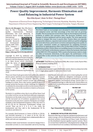
International Journal of Trend in Scientific Research and Development (IJTSRD) ISSN: 2456-6470 According to the Fourier analysis, a non-sinusoidal voltage and current can be expressed by the sum of sinusoidal functions in different frequencies with different amplitudes. The active power resulting from this non-sinusoidal voltage and current is defined as the mean value of the product of voltage and current. Since the integrals of all the cross product of terms with different frequencies are zero. The active power at different frequencies is isolated from each other and the voltage or current in one frequency has no influence on the active power at other frequencies. The independency of the active power at different frequencies gives the possibility that a converter without power source can generate active power at one frequency and absorb this power from other frequencies. By applying this method to the DPFC, the shunt converter can absorb active power from the grid at the fundamental frequency and inject the current back into the grid at a harmonic frequency. This harmonic current will flow through the transmission line. According to the amount of required active power at the fundamental frequency, the DPFC series converters generate a voltage at the harmonic frequency, thereby absorbing the active power from harmonic components. Assuming a lossless converter, the active power generated at fundamental frequency is equal to the power absorbed from the harmonic frequency. The high-pass filter within the DPFC blocks the fundament frequency components and allows the harmonic components to pass, thereby providing a return path for the harmonic components. The shunt and series converters, the high-pass filter, and the ground form the closed loop for the harmonic current. Fig. 1. Basic block diagram of DPFC II. BASIC PRINCIPLE OF DPFC Two approaches are applied to the UPFC to increase the reliability and to reduce the cost; they are as follows. First, eliminating the common dc link of the UPFC and second distributing the series converter, as shown in Fig. 2. By combining these two approaches, the new FACTS device—DPFC is achieved. The DPFC consists of one shunt and several series- connected converters. The shunt converter is similar as a STATCOM, while the series converter employs the D-FACTS concept, which is to use multiple single- phase converters instead of one large rated converter. Each converter within the DPFC is independent and has its own dc capacitor to provide the required dc voltage. Fig. 2. Flowchart from UPFC to DPFC. As shown, besides the key components, namely the shunt and series converters, the DPFC also requires a high-pass filter that is shunt connected at the other side of the transmission line, and two Y–Δ transformers at each side of the line. The reason for these extra components will be explained later. The unique control capability of the UPFC is given by the back-to- back connection between the shunt and series converters, which allows the active power to exchange freely. To ensure that the DPFC have the same control capability as the UPFC, a method that allows the exchange of active power between converters with eliminated dc link is the prerequisite. Due to the unique characters of third-harmonic frequency components, the third harmonic is selected to exchange the active power in the DPFC. In a three- phase system, the third harmonic in each phase is identical, which is referred to as “zero-sequence.” The zero-sequence harmonic can be naturally blocked by Y–Δ transformers, which are widely used in power system to change voltage level. Therefore, there is no extra filter required to prevent the harmonic leakage to the rest of the network. In addition, by using the third harmonic, the costly high-pass filter can be replaced by a cable that is connected between the neutral point of the Y–Δ transformer on the right side in Fig. 3 and the ground. Because the Δ winding appears open circuit to the third-harmonic current, all harmonic current will flow through the Y-winding and concentrate to the grounding cable. Therefore, the A. Eliminate DC link Within the DPFC, there is a common connection between the ac terminals of the shunt and the series converters, which is the transmission line. Therefore, it is possible to exchange the active power through the ac terminals of the converters. The method is based on the power theory of non-sinusoidal components. @ IJTSRD | Available Online @ www.ijtsrd.com | Volume – 2 | Issue – 4 | May-Jun 2018 Page: 56
International Journal of Trend in Scientific Research and Development (IJTSRD) ISSN: 2456-6470 large-size high-pass filter is eliminated. Another advantage of using third harmonic to exchange active power is that the way of grounding of Y–Δ transformers can be used to route the harmonic current in a meshed network. If the branch requires the harmonic current to flow through, the neutral point of the Y–Δ transformer at the other side in that branch will be grounded and vice versa. Because the transformer of the line without the series converter is floating, it is open circuit for third-harmonic components. Therefore, no third-harmonic current will flow through this line. Theoretically, the third-, sixth-, and ninth-harmonic frequencies are all zero-sequence, and all can be used to exchange active power in the DPFC. As it is well known, the capacity of a transmission line to deliver power depends on its impedance. Since the transmission-line impedance is inductive and proportional to the frequency, high- transmission frequencies will cause high impedance. Consequently, the zero-sequence harmonic with the lowest frequency—third harmonic is selected. The power and voltage rating of each unit is relatively small. Further, the units are clamped on transmission lines, and therefore, no land is required. The redundancy of the D-FACTS uninterrupted operation during a single module failure, thereby giving a much higher reliability than other FACTS devices. provides an III. CONTROL OF DPFC The DPFC has three control strategies: central controller, series control, and shunt control, as shown in Fig. 3. A. Central Control This controller manages all the series and shunt controllers and sends reference signals to both of them. B. Series Controller Each single-phase converter has its own series control through the line. The controller inputs are series capacitor voltages, line current, and series voltage reference in the d-q frame. B. Distributed Series Converter The D-FACTS is a solution for the series-connected FACTS, which can dramatically reduce the total cost and increase the reliability of the series FACTS device. The idea of the D-FACTS is to use a large number of controllers with low rating instead of one large rated controller. The small controller is a single- phase converter attached to transmission lines by a single-turn transformer. The converters are hanging on the line so that no costly high-voltage isolation is required. The single-turn transformer uses the transmission line as the secondary winding, inserting controllable impedance into the line directly. Each D- FACTS module is self-powered from the line and controlled remotely by wireless or power-line communication. The block diagram of the series converters in MATLAB/Simulink environment is demonstrated in Fig. 4. Any series controller has a low-pass and a 3rd-pass filter to create fundamental and third harmonic current, respectively. Two single-phase phase lock loop (PLL) are used to take frequency and phase information from network [11]. C. Shunt controller The shunt converter includes a three-phase converter connected back-to-back to a single-phase converter. The three-phase converter absorbs active power from grid at fundamental frequency and controls the dc voltage of capacitor between this converter and single-phase one. Other task of the shunt converter is to inject constant third-harmonic current into lines through the neutral cable of Δ-Y transformer as shown in Fig. 5. The structure of the D-FACTS results in low cost and high reliability. As D-FACTS units are single-phase devices floating on lines, high-voltage isolations between phases are avoided. The unit can easily be applied at any transmission-voltage level, because it does not require supporting phase-ground isolation. @ IJTSRD | Available Online @ www.ijtsrd.com | Volume – 2 | Issue – 4 | May-Jun 2018 Page: 57
International Journal of Trend in Scientific Research and Development (IJTSRD) ISSN: 2456-6470 Goto1 z Goto2 z Fig. 4. MATLAB/Simulink diagram of series controller Fig. 5. MATLAB/Simulink diagram of shunt controller @ IJTSRD | Available Online @ www.ijtsrd.com | Volume – 2 | Issue – 4 | May-Jun 2018 Page: 58
International Journal of Trend in Scientific Research and Development (IJTSRD) ISSN: 2456 Scientific Research and Development (IJTSRD) ISSN: 2456 Scientific Research and Development (IJTSRD) ISSN: 2456-6470 IV. The whole model of system under study contains a three-phase source connected to a nonlinear RLC load through parallel transmission lines (Line 1 and Line 2) with the same lengths. The DPFC is placed in transmission line, which the shunt converter is connected to the transmission line 2 in parallel through a Y-Δ three-phase transformer, and series converters is distributed through this line. converters is distributed through this line. RESULTS AND DISCUSSION RESULTS AND DISCUSSION high current is drawn by the load. It is undesirable as the transmission line has limited current carrying capacity ad this high current can overheat the high current is drawn by the load. It is undesirable as the transmission line has limited current carrying capacity ad this high current can overheat the transmission lines also can damage them transmission lines also can damage them The whole model of system under study contains a phase source connected to a nonlinear RLC load through parallel transmission lines (Line 1 and Line 2) with the same lengths. The DPFC is placed in rce voltage waveform also there is significant drop in the voltage. The source current is sinusoidal in nature, increasing the harmonic From the source voltage waveform also there is significant drop in the voltage. The source current is also non-sinusoidal in nature, increasing the harmonic contents in the supply current. contents in the supply current. shunt converter is connected to the transmission line 2 in parallel phase transformer, and series To overcome these problems, DPFC is connected in the transmission line. When the fault occurs, DPFC compensate the load current and load voltage same can be seen in the Fig. 10 to Fig. 13. , the source side the current and voltage waveform has significant improvement in terms of magnitude as well as To overcome these problems, DPFC is connected in the transmission line. When t compensate the load current and load voltage same can be seen in the Fig. 10 to Fig. 13. , the source side the current and voltage waveform has significant improvement in terms of magnitude as well as harmonics contents. To simulate the dynamic performance, a three fault is considered on the system. The tim the fault is 0.1 seconds (200-300 millisecond). As shown in Fig. 6, a significant voltage sag is observable during the compensation. This sag can reduce the performance of the device connected on same line. In the current waveform (Fig.7) also it can be observed that very aveform (Fig.7) also it can be observed that very To simulate the dynamic performance, a three-phase fault is considered on the system. The time duration of 300 millisecond). As shown in Fig. 6, a significant voltage sag is observable during the compensation. This sag can reduce the performance of the device connected on same line. In the current fault, fault, without without any any Fig. 6. Load voltage w Fig. 6. Load voltage without DPFC Fig. 7. Load current without DPFC Fig. 7. Load current without DPFC @ IJTSRD | Available Online @ www.ijtsrd.com @ IJTSRD | Available Online @ www.ijtsrd.com | Volume – 2 | Issue – 4 | May-Jun Jun 2018 Page: 59
International Journal of Trend in Scientific Research and Development (IJTSRD) ISSN: 2456 Scientific Research and Development (IJTSRD) ISSN: 2456 Scientific Research and Development (IJTSRD) ISSN: 2456-6470 Fig. 8. Source voltage without DPFC Fig. 8. Source voltage without DPFC Fig. 9. Source current without DPFC Fig. 9. Source current without DPFC Fig. Fig.10. Load voltage with DPFC Fig. 11. Fig. 11. Load current with DPFC @ IJTSRD | Available Online @ www.ijtsrd.com @ IJTSRD | Available Online @ www.ijtsrd.com | Volume – 2 | Issue – 4 | May-Jun Jun 2018 Page: 60
International Journal of Trend in Scientific Research and Development (IJTSRD) ISSN: 2456 Scientific Research and Development (IJTSRD) ISSN: 2456 Scientific Research and Development (IJTSRD) ISSN: 2456-6470 Fig. 12. Fig. 12. Source voltage with DPFC Fig. 13. Fig. 13. Source current with DPFC V. CONCLUSIONS To improve power quality in the power transmission system, there are some effective methods. In this paper, the voltage sag and swell mitigation, using a new FACTS device called distributed power flow controller (DPFC) is presented. o improve power quality in the power transmission system, there are some effective methods. In this paper, the voltage sag and swell mitigation, using a new FACTS device called distributed power flow References 1)Y.-H. Transmission Systems (FACTS) (IEE Power and Energy Series), vol. 30. London, U.K.: Institution of Electrical Engineers, 1999. of Electrical Engineers, 1999. H. Song Song and and A. Johns, A. Johns, Flexible Flexible ac Transmission Systems (FACTS) (IEE Power and Energy Series), vol. 30. London, U.K.: Institution The DPFC structure is similar to unified power flow controller (UPFC) and has a same control capability to balance the line parameters, i.e., line impedance, transmission angle, and bus voltage magnitude. However, the DPFC offers some advantages, in comparison with UPFC, such as high control capability, high reliability, and low cost. The DPFC is modeled and three control loops, i.e., central controller, series control, and shunt control are design. The system under study is a single machine infinite bus system, with and without DPFC. To simulate the dynamic performance, a three-phase fault is considered near the load. It is shown that the DPFC gives an acceptable performance in power quality mitigation and power flow control. is similar to unified power flow 2)N. G. Hingorani and L. Gyugyi, Understanding FACTS : Concepts and Technology of Flexible AC Transmission Systems. New York Press, 2000. N. G. Hingorani and L. Gyugyi, Understanding FACTS : Concepts and Technology of Flexible AC Transmission Systems. New York: IEEE controller (UPFC) and has a same control capability to balance the line parameters, i.e., line impedance, transmission angle, and bus voltage magnitude. However, the DPFC offers some advantages, in 3)L.Gyugyi, C.D. Schauder, S. L.Williams, T. R. Rietman,D. R. Torgerson, andA. Edris, “The unified power flowcontroller:Anewapproach to power transmission control,” IEEE Trans. Power Del., vol. 10, no. 2, pp. 1085 Del., vol. 10, no. 2, pp. 1085– 1097, Apr. 1995. L.Gyugyi, C.D. Schauder, S. L.Williams, T. R. Rietman,D. R. Torgerson, andA. Edris, “The unified power flowcontroller:Anewapproach to power transmission control,” IEEE Trans. Power h as high control capability, high reliability, and low cost. The DPFC is modeled and three control loops, i.e., central controller, series control, and shunt control are design. The system under study is a single machine infinite- out DPFC. To simulate the 4)A.-A. Edris, “Proposed terms and definitions for flexible ac transmission system (facts),” IEEE Trans. Power Del., vol. 12, no. 4, pp. 1848 Oct. 1997. A. Edris, “Proposed terms and definitions for flexible ac transmission system (facts),” IEEE Trans. Power Del., vol. 12, no. 4, pp. 1848–1853, phase fault is considered near the load. It is shown that the DPFC gives an acceptable performance in power quality @ IJTSRD | Available Online @ www.ijtsrd.com @ IJTSRD | Available Online @ www.ijtsrd.com | Volume – 2 | Issue – 4 | May-Jun Jun 2018 Page: 61
International Journal of Trend in Scientific Research and Development (IJTSRD) ISSN: 2456-6470 5)K. K. Sen, “Sssc-static synchronous series compensator: Theory, modeling and application,” IEEE Trans. Power Del., vol. 13, no. 1, pp. 241– 246 Jan. 1998. 8)Y. Zhihui, S.W. H. de Haan, and B. Ferreira, “Utilizing distributed powe flow controller (dpfc) for power oscillation damping,” in Proc. IEEE Power Energy Soc. Gen. Meet. (PES), 2009, pp. 1–5. 6)M. D. Deepak, E. B. William, S. S. Robert, K. Bill, W. G. Randal, T. B. Dale, R. I. Michael, and S. G. Ian, “A distributed static series compensator system for realizing active power flow control on existing power lines,” IEEE Trans. Power Del., vol. 22, no. 1, pp. 642–649, Jan. 2007. 9)Y. Zhihui, S. W. H. de Haan, and B. Ferreira, “Dpfc control during shunt converter failure,” in Proc. IEEE Energy Convers. Congr. Expo. (ECCE), 2009, pp. 2727–2732. 10)Y. Sozer and D. A. Torrey, “Modeling and control of utility interactiv inverters,” IEEE Trans. Power 7)D. Divan and H. Johal, “Distributed facts—A new concept for realizing grid power flow control,” in Proc. IEEE 36th Power Electron. Spec. Conf. (PESC), 2005, pp. 8–14. 11)Electron., vol. 24, no. 11, pp. 2475–2483, Nov. 2009. @ IJTSRD | Available Online @ www.ijtsrd.com | Volume – 2 | Issue – 4 | May-Jun 2018 Page: 62