Download
1 / 5
50 likes | 107 Views
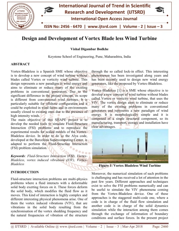
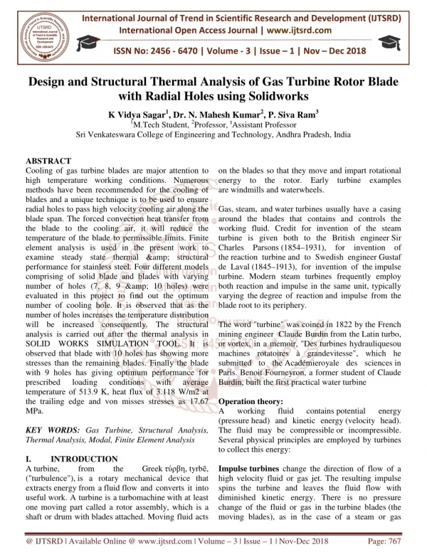
Cooling of gas turbine blades are major attention to high temperature working conditions. Numerous methods have been recommended for the cooling of blades and a unique technique is to be used to ensure radial holes to pass high velocity cooling air along the blade span. The forced convection heat transfer from the blade to the cooling air, it will reduce the temperature of the blade to permissible limits. Finite element analysis is used in the present work to examine steady state thermal andamp structural performance for stainless steel. Four different models comprising of solid blade and blades with varying number of holes 7, 8, 9 andamp 10 holes were evaluated in this project to find out the optimum number of cooling hole. It is observed that as the number of holes increases the temperature distribution will be increased consequently. The structural analysis is carried out after the thermal analysis in SOLID WORKS SIMULATION TOOL. It is observed that blade with 10 holes has showing more stresses than the remaining blades. Finally the blade with 9 holes has giving optimum performance for prescribed loading conditions with average temperature of 513.9 K, heat flux of 3.118 W m2 at the trailing edge and von misses stresses as 17.67 MPa. K Vidya Sagar | Dr. N. Mahesh Kumar | P. Siva Ram "Design and Structural Thermal Analysis of Gas Turbine Rotor Blade with Radial Holes using Solidworks" Published in International Journal of Trend in Scientific Research and Development (ijtsrd), ISSN: 2456-6470, Volume-3 | Issue-1 , December 2018, URL: https://www.ijtsrd.com/papers/ijtsrd19077.pdf Paper URL: http://www.ijtsrd.com/engineering/mechanical-engineering/19077/design-and-structural-thermal-analysis-of-gas-turbine-rotor-blade-with-radial-holes-using-solidworks/k-vidya-sagar<br>

E N D
International Journal of Trend in International Open Access International Open Access Journal | www.ijtsrd.com International Journal of Trend in Scientific Research and Development (IJTSRD) Research and Development (IJTSRD) www.ijtsrd.com ISSN No: 2456 ISSN No: 2456 - 6470 | Volume - 3 | Issue – 1 | Nov 1 | Nov – Dec 2018 Design and Structural Thermal Analysis with Radial Holes Structural Thermal Analysis of Gas Turbine Radial Holes using Solidworks Gas Turbine Rotor Blade K Vidya Sagar1, Dr. N. Mahesh Kumar2, P. Siva Ram3 Tech Student, 2Professor,3Assistant Professor K Vidya Sagar 1M.Tech Student Sri Venkateswara College Sri Venkateswara College of Engineering and Technology, Andhra Pradesh Andhra Pradesh, India ABSTRACT Cooling of gas turbine blades are major attention to high temperature working conditions. Numerous methods have been recommended for the cooling of blades and a unique technique is to be used to ensure radial holes to pass high velocity cooling air along t blade span. The forced convection heat transfer from the blade to the cooling air, it will reduce the temperature of the blade to permissible limits. Finite element analysis is used in the present work to examine steady state thermal & structural performance for stainless steel. Four different models comprising of solid blade and blades with varying number of holes (7, 8, 9 & 10 holes) were evaluated in this project to find out the optimum number of cooling hole. It is observed that as the number of holes increases the temperature distribution will be increased consequently. The structural analysis is carried out after the thermal analysis in SOLID WORKS SIMULATION TOOL. It is observed that blade with 10 holes has showing more stresses than the remaining blades. Finally the blade with 9 holes has giving optimum performance for prescribed loading conditions temperature of 513.9 K, heat flux of 3.118 W/m2 at the trailing edge and von misses stresses as 17.67 MPa. KEY WORDS: Gas Turbine, Structural A Thermal Analysis, Modal, Finite Element Analysis I. INTRODUCTION A turbine, from the ("turbulence"), is a rotary mechanical device that extracts energy from a fluid flow and converts it into useful work. A turbine is a turbomachine one moving part called a rotor assembly, which is a shaft or drum with blades attached. Moving fluid acts attached. Moving fluid acts on the blades so that they move and energy to the rotor. Early turbine examples are windmills and waterwheels Gas, steam, and water turbines usually have a casing around the blades that contains and controls working fluid. Credit for invention of the steam turbine is given both to the British engineer Charles Parsons (1854–1931), for invention of the reaction turbine and to Swedish engineer de Laval (1845–1913), for invention of the turbine. Modern steam turbines frequently employ both reaction and impulse in the same unit, typically varying the degree of reaction blade root to its periphery. The word "turbine" was coined in 1822 by the French mining engineer Claude Burdin or vortex, in a memoir, "Des turbines hydrauliquesou machines rotatoires à grandevitesse", which he submitted to the Académieroyale des sciences Paris. Benoit Fourneyron, a former student of Claude Burdin, built the first practical Operation theory: A working fluid contains (pressure head) and kinetic energy The fluid may be compressible Several physical principles are employed by turbines to collect this energy: Impulse turbines change the direction of flow of a high velocity fluid or gas jet. The resulting impulse spins the turbine and leaves the fluid flow with diminished kinetic energy. There is no pressure change of the fluid or gas in the moving blades), as in the case of a steam or gas moving blades), as in the case of a steam or gas Cooling of gas turbine blades are major attention to high temperature working conditions. Numerous methods have been recommended for the cooling of blades and a unique technique is to be used to ensure radial holes to pass high velocity cooling air along the blade span. The forced convection heat transfer from the blade to the cooling air, it will reduce the temperature of the blade to permissible limits. Finite element analysis is used in the present work to examine steady state thermal & structural rformance for stainless steel. Four different models comprising of solid blade and blades with varying number of holes (7, 8, 9 & 10 holes) were evaluated in this project to find out the optimum number of cooling hole. It is observed that as the of holes increases the temperature distribution will be increased consequently. The structural analysis is carried out after the thermal analysis in SOLID WORKS SIMULATION TOOL. It is observed that blade with 10 holes has showing more maining blades. Finally the blade with 9 holes has giving optimum performance for prescribed loading conditions temperature of 513.9 K, heat flux of 3.118 W/m2 at the trailing edge and von misses stresses as 17.67 on the blades so that they move and impart rotational Early turbine examples waterwheels. turbines usually have a casing around the blades that contains and controls the working fluid. Credit for invention of the steam turbine is given both to the British engineer Sir 1931), for invention of and to Swedish engineer Gustaf 1913), for invention of the impulse . Modern steam turbines frequently employ both reaction and impulse in the same unit, typically degree of reaction and impulse from the The word "turbine" was coined in 1822 by the French Burdin from the Latin turbo, , in a memoir, "Des turbines hydrauliquesou machines rotatoires à grandevitesse", which he Académieroyale des sciences in , a former student of Claude actical water turbine with with average average working fluid contains potential kinetic energy (velocity head). compressible or incompressible. energy Gas Turbine, Structural Analysis, Thermal Analysis, Modal, Finite Element Analysis Several physical principles are employed by turbines from is a rotary mechanical device that flow and converts it into turbomachine with at least one moving part called a rotor assembly, which is a , the Greek Greek τύρβη, tyrbē, change the direction of flow of a high velocity fluid or gas jet. The resulting impulse spins the turbine and leaves the fluid flow with diminished kinetic energy. There is no pressure change of the fluid or gas in the turbine blades (the @ IJTSRD | Available Online @ www.ijtsrd.com www.ijtsrd.com | Volume – 3 | Issue – 1 | Nov-Dec 2018 Dec 2018 Page: 767
International Journal of Trend in Scientific Research and Development (IJTSRD) ISSN: 2456 International Journal of Trend in Scientific Research and Development (IJTSRD) ISSN: 2456 International Journal of Trend in Scientific Research and Development (IJTSRD) ISSN: 2456-6470 turbine; the entire pressure drop takes place in the stationary blades (the nozzles). Before reaching the turbine, the fluid's pressure to velocity head by accelerating the fluid a nozzle. Pelton wheels and de Laval turbines process exclusively. Impulse turbines do not require a pressure casement around the rotor since the fluid jet is created by the nozzle prior to reaching the blading on the rotor. Newton's second law transfer of energy for impulse turbines. Reaction turbines develop torque by reacting to the gas or fluid's pressure or mass. The pressure of the gas or fluid changes as it passes through the turbine rotor blades. A pressure casement is needed to contain the working fluid as it acts on the turbine stage(s) or the turbine must be fully immersed in the fluid flow (such as with wind turbines). The casing contains and directs the working fluid and, for water turbines, maintains the suction tube. Francis turbines and most steam turbines this concept. For compressible working fluids, multiple turbine stages are usually used to harness the expanding gas efficiently. Newton's law describes the transfer of energy for turbines. pressure drop takes place in the entire unit running. The compressor module, combustor module and turbine module connected by collectively called the gas the entire unit running. The compressor module, combustor module and turbine module connected by one or more shafts are collectively called the gas generator. III. LITERATURE REVIEW Mohammad H. Albeirutty: in their paper discussed that the heat transfer analysis of gas turbine blades using air or steam as coolants is investigated under various operating conditions. A general model of the combined system is developed and is used to compare the performance of three main schemes of the blade cooling, namely air-cooling, open cooling (OCSC) and closed (CLSC). The heat transfer model permitted the calculations of the cooling mass ratio that is required to reach a certain blade tem showed that steam appears to be a potential cooling medium, when employed in an open closed-loop scheme. The combined system with CLSC gives better overall performance than does air cooling or the OCSC. Gowrishankar: in their paper discussed that Withstanding of gas turbine blades for the elongations is a major consideration in their design because they are subjected to high tangential, axial, centrifugal forces during their working conditions. The first stage rotor blade of a two - stage gas turbine has been analyzed for structural, thermal using ANSYS 12 which is powerful Finite Element Software. In the process of getting the thermal stresses, the temperature distribution in the rotor blade has been evaluated using this software. This project specifies how the program makes effective use of the ANSYS pre-processor to analyze the complex turbine blade geometries and apply boundary conditions to examine steady state thermal & structural performance of the blade for N 155, Hastealloy x & Inconel 625 materials. IV. MODELLING OF GAS TURBINE Modeling of Blade in SolidWorks of Blade in SolidWorks: stationary blades (the nozzles). Before reaching the pressure by accelerating the fluid with head head is changed de Laval turbines use this LITERATURE REVIEW process exclusively. Impulse turbines do not require a pressure casement around the rotor since the fluid jet is created by the nozzle prior to reaching the blading in their paper discussed that the heat transfer analysis of gas turbine blades using air or steam as coolants is investigated under various operating conditions. A general model of the combined system is developed and is used to compare three main schemes of the blade cooling, open-circuit steam cooling (OCSC) and closed-loop steam cooling (CLSC). The heat transfer model permitted the calculations of the cooling mass ratio that is required to reach a certain blade temperature. The results showed that steam appears to be a potential cooling medium, when employed in an open-circuit or in a loop scheme. The combined system with CLSC gives better overall performance than does air- describes the by reacting to the gas or fluid's pressure or mass. The pressure of the gas or fluid changes as it passes through the turbine rotor eded to contain the working fluid as it acts on the turbine stage(s) or the turbine must be fully immersed in the fluid flow (such as with wind turbines). The casing contains and directs the working fluid and, for water turbines, imparted rted steam turbines use by by the the draft this concept. For compressible working fluids, multiple turbine stages are usually used to harness the Newton's third third in their paper discussed that describes the transfer of energy for reaction Withstanding of gas turbine blades for the elongations is a major consideration in their design because they are subjected to high tangential, axial, centrifugal forces during their working conditions. The first stage stage gas turbine has been analyzed for structural, thermal using ANSYS 12 which is powerful Finite Element Software. In the process of getting the thermal stresses, the temperature distribution in the rotor blade has been is software. This project specifies how the program makes effective use of the ANSYS the complex turbine blade geometries and apply boundary conditions to examine steady state thermal & structural performance of the , Hastealloy x & Inconel 625 Figure 1: Impulse and reaction turbine mpulse and reaction turbine II. The gas turbine is the most versatile item of turbomachinery today. It can be used in several different modes in critical industries such a generation, oil and gas, process plants, aviation, as well domestic and smaller related industries. A gas turbine essentially brings together air that it compresses in its compressor module, and fuel, that are then ignited. Resulting gases are expanded through a turbine. That turbine’s shaft continues to rotate and drive the compressor which is on the same shaft, and operation continues. A separator starter unit is used to provide the first rotor motion, until the turbine’s rotation is up to design speed and can keep turbine’s rotation is up to design speed and can keep INTRODUCTION TO GAS TURBINE TO GAS TURBINE The gas turbine is the most versatile item of turbomachinery today. It can be used in several different modes in critical industries such as power process plants, aviation, as well domestic and smaller related industries. A gas turbine essentially brings together air that it compresses in its compressor module, and fuel, that are then ignited. Resulting gases are expanded . That turbine’s shaft continues to rotate and drive the compressor which is on the same shaft, and operation continues. A separator starter unit is used to provide the first rotor motion, until the MODELLING OF GAS TURBINE Figure 2: orthographic views of gas turbine blade : orthographic views of gas turbine blade @ IJTSRD | Available Online @ www.ijtsrd.com www.ijtsrd.com | Volume – 3 | Issue – 1 | Nov-Dec 2018 Dec 2018 Page: 768
International Journal of Trend in Scientific Research and Development (IJTSRD) ISSN: 2456 International Journal of Trend in Scientific Research and Development (IJTSRD) ISSN: 2456 International Journal of Trend in Scientific Research and Development (IJTSRD) ISSN: 2456-6470 Now the gas turbine blade with holes 7, 8 has been modeled as shown below 7, 8 , 9 and 10 Table1. Types of simulations in SolidWorks Table1. Types of simulations in SolidWorks Study type Study type Modal Time History Study icon Study icon Static Frequency Harmonic Harmonic Random Vibration Response Spectrum Drop Test Buckling Thermal Design Study Nonlinear Static Figure 3: Gas turbine blade of 7 as turbine blade of 7 holes Fatigue Pressure Vessel Design Nonlinear Dynamic Static Analysis: When loads are applied to a body, the body deforms and the effect of loads is transmitted throughout the body. The external loads induce internal forces and reactions to render the body into a state of equilibrium. Linear Static displacements, strains, stresses, and reaction forces under the effect of applied loads Thermal Stress Analysis: Changes in temperature can induce substantial deformations, strains, and stresses. Thermal stress analysis refers to static analysis that includes the effect of temperature. Perform thermal stress analysis using one of the following options: ?Using a uniform rise or drop in temperature for the whole model. ?Using a temperature profile resulting from a steady state or transient thermal analysis. ?Using a temperature profile from Flow Simulation loads are applied to a body, the body deforms and the effect of loads is transmitted throughout the body. The external loads induce internal forces and reactions to render the body into a state of equilibrium. Linear Static s, strains, stresses, and reaction forces under the effect of applied loads. analysis analysis calculates calculates Figure 4: Gas turbine blade of 8 as turbine blade of 8 holes Changes in temperature can induce substantial deformations, strains, and stresses. Thermal stress analysis refers to static analysis that includes the Perform thermal stress analysis using one of the Using a uniform rise or drop in temperature for Using a temperature profile resulting from a steady state or transient thermal analysis. mperature profile from Flow Simulation Figure 5: Gas turbine blade of 9 as turbine blade of 9 holes Figure 7: Meshed model of gas turbine blade with 7 holes eshed model of gas turbine blade with 7 Figure 6: Gas turbine blade of 10 as turbine blade of 10 holes @ IJTSRD | Available Online @ www.ijtsrd.com www.ijtsrd.com | Volume – 3 | Issue – 1 | Nov-Dec 2018 Dec 2018 Page: 769
International Journal of Trend in Scientific Research and Development (IJTSRD) ISSN: 2456 International Journal of Trend in Scientific Research and Development (IJTSRD) ISSN: 2456 International Journal of Trend in Scientific Research and Development (IJTSRD) ISSN: 2456-6470 Table2. Mesh Information Mesh Information Figure 11: Strain Strain VI. THERMAL THERMAL TURBINE BLADE ANALYSIS ANALYSIS OF OF GAS GAS V. STRUCTURAL TURBINE BLADE STRUCTURAL ANALYSIS ANALYSIS OF OF GAS GAS Figure 8: Loads & Fixtures Figure 8: Loads & Fixtures Figure 12: Heat Flux o : Heat Flux of Gas Turbine VII. Table 3: comparison of average temperatures trailing edge of blades with different holes trailing edge of blades with different holes RESULTS Table 3: comparison of average temperatures at the Average temperature Average temperature at the trailing edge at the trailing edge 516.1k 515.12k 513.9k 513.2k Blade with holes Figure 9: VON misses stress stress 7 holes blade 8 holes blade 9 holes blade 10 holes blade Table 4: comparison of Heat flux developed in blades Average Heat-Flux Table 4: comparison of Heat flux developed in blades Blade with holesAverage Heat 7 holes blade 8 holes blade 9 holes blade 10 holes blade 2.999 w/m2 3.447 w/m2 3.118 w/m2 4.263 w/m2 Figure10: Displacement @ IJTSRD | Available Online @ www.ijtsrd.com www.ijtsrd.com | Volume – 3 | Issue – 1 | Nov-Dec 2018 Dec 2018 Page: 770
International Journal of Trend in Scientific Research and Development (IJTSRD) ISSN: 2456 International Journal of Trend in Scientific Research and Development (IJTSRD) ISSN: 2456 International Journal of Trend in Scientific Research and Development (IJTSRD) ISSN: 2456-6470 Table 5: comparison of von misses stresses developed in blades Blade with holesVon misses stresses [Mpa] 7 holes 8 holes 9 holes 10 holes CONCLUSION In this project using finite element analysis as a tool, the thermal and structural analysis is carried out sequentially. The blade with different no. 8, 9and 10 were used for analysis. ?The gas turbine blade is modeled in called Solidworks 2014by using extrude feature. ?Then gas turbine blade with different holes such as 7, 8, 9 and 10 has been modeled on the blade span. ?The blade with different no. of holes 7, 8, 9and 10 were used for thermal analysis in simulation tool. It is observed that as the no. of holes increases the temperature distribution increase. ?The structural analysis is carried out after the thermal analysis SIMULATION TOOL.It is observed that blade with 10 holes has showing more stresses than the remaining blades. REFERENCES 1.Gowreesh, S., Sreenivasalu Reddy, N. and Yogananda Murthy, NV. 2009. Convective Heat Transfer Analysis of a Aero Gas Blade Using Ansys, International of Mechanic and Solids. 4: 39-46. 2.Facchini, B. and Stecco. S.S. 1999.Cooled expansion in gas turbines: a comparison of analysis methods, Energy Conversion and Management. 40: 1207-1224. 3.Mohammad, H., Albeirutty. Alghamdi., Youssef, S. Najjar. 2004. Heat analysis for a multistage gas turbine Table 5: comparison of von misses stresses developed different blade-cooling scheme Engineering. 24: 563-577. 4.Mahfoud, K. and George, B. 1997. study of turbine blade cooling by a gas, Applied Thermal Engineering. 1141-1149. 5.Moyroud, F., Fransson, T. and Jacquet G. 2002. A comparison reduction techniques for mistuned Journal of Engineering for Gas Power. 124: 942-953. 6.Giovanni, C., Ambra, G., Lorenzo, B. and Roberto, F. 2007Advances in effusive cooling techniques of gas turbines, Engineering. 27: 692-698. 7.Cun-liang, L., Hui-ren, Z., Jiang chun, X. 2010.Film cooling performance of converging slot-hole rows on a International Journal Transfer.53: 5232-5241. 8.Zhang, JJ., Esat, II. And Analysis with VaryingMesh Stiffness, and Structures. 70: 273-280. 9.Hildebrabd, FB. 1997. Introduction to Analysis, McGraw-Hill, New York. 10.MoussaviTorshizi, SE., YadavarNikravesh and Jahangiri,A. 2009. Failure analysis of gas turbine generator cooling fan Failure Analysis. 16: 1686 11.Cleeton, JPE., Kavanagh, RM. and Parks, GT. 2009. Blade cooling optimization steam-injected gas turbines Engineering. 29: 3274-3283. 12.Krishnamoorthy, C. Analysis Theory and McGraw-Hill, New Delhi. 13.Martin, HC. and Carey, GF. 2006. Introduction the Finite Element Analysis, McGraw Publishing Co Ltd, New Delhi. Ltd, New Delhi. cooling scheme, Applied Thermal Von misses stresses [Mpa] ge, B. 1997. Computational blade cooling by slot-injection of Engineering. 17: 15.6 19.6 17.67 28.6 17.67 Moyroud, F., Fransson, T. and Jacquet-Richardet, of two finite element or mistuned bladed-disks, nite element analysis as a tool, Journal of Engineering for Gas Turbines and the thermal and structural analysis is carried out with different no. of holes 7, Giovanni, C., Ambra, G., Lorenzo, B. and Roberto, F. 2007Advances in effusive cooling techniques of gas turbines, Applied Thermal modeled in a 3D cad tool by using extrude feature. Then gas turbine blade with different holes such and 10 has been modeled on the blade ren, Z., Jiang-tao, B. and Du- chun, X. 2010.Film cooling performance of hole rows on a gas turbine blade, International Journal The blade with different no. of holes 7, 8, 9and 10 were used for thermal analysis in SolidWorks simulation tool. It is observed that as the no. of holes increases the temperature distribution of of Heat Heat and and Mass Mass And Shi, YH. 1999. Load Analysis with VaryingMesh Stiffness, Computers 280. The structural analysis is carried out after the in It is observed that blade stresses than the SOLID SOLID WORKS WORKS Hildebrabd, FB. 1997. Introduction to Numerical Hill, New York. , YadavarNikravesh, SM. . 2009. Failure analysis of gas turbine generator cooling fan blades, Engineering Failure Analysis. 16: 1686-1695. Gowreesh, S., Sreenivasalu Reddy, N. and NV. 2009. Convective Heat Turbine Cleeton, JPE., Kavanagh, RM. and Parks, GT. optimization in humid-air and gas turbines, Applied Thermal 3283. ternational Journal Facchini, B. and Stecco. S.S. 1999.Cooled : a comparison of Conversion and Krishnamoorthy, C. 1994. 1994. Finite Finite Element Element Tata Programming, Hill, New Delhi. Abdullah, Abdullah, S., S., Martin, HC. and Carey, GF. 2006. Introduction to Analysis, McGraw Hill Najjar. 2004. Heat transfer turbine using @ IJTSRD | Available Online @ www.ijtsrd.com www.ijtsrd.com | Volume – 3 | Issue – 1 | Nov-Dec 2018 Dec 2018 Page: 771