Download
1 / 4
40 likes | 65 Views
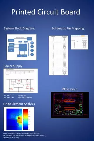
In this system, an Arduino based 3 axis CNC drilling machine for printed circuit board is implemented using Arduino controller, CNC router and open source software for controlling the whole operation. This can be the invention for the electronic industries and electronic students which can design the production as desired. This CNC machine is able to draw a circuit layout on PCB or any other solid surface using simple algorithm and available components. At first, the user need to design PCB layout using eagle software which is directly generated G code and then feed it to the machine using candle software. Arduino Uno with an AT mega 328 microcontroller is used as main controller for this system. The microcontroller converts G code into a set of machine language instruction to be sent to the motor driver of the CNC machine. This system can provide to drill in less time and increase the flexibility. Moe Myint Aung | Nwe Nwe Oo | May Thwe Oo "CNC Drilling Machine for Printed Circuit Board" Published in International Journal of Trend in Scientific Research and Development (ijtsrd), ISSN: 2456-6470, Volume-3 | Issue-5 , August 2019, URL: https://www.ijtsrd.com/papers/ijtsrd25290.pdf Paper URL: https://www.ijtsrd.com/engineering/electronics-and-communication-engineering/25290/cnc-drilling-machine-for-printed-circuit-board/moe-myint-aung<br>

E N D
International Journal of Trend in Scientific Research and Development (IJTSRD) Volume 3 Issue 5, August 2019 Available Online: www.ijtsrd.com e-ISSN: 2456 – 6470 CNC Drilling Machine for Printed Circuit Board Moe Myint Aung1, Nwe Nwe Oo1, May Thwe Oo2 1Lecturer,2Professor 1,2Department of Electronic Engineering, Technological University (Magway), Myanmar How to cite this paper: Moe Myint Aung | Nwe Nwe Oo | May Thwe Oo "CNC Drilling Machine for Printed Circuit Board" Published in International Journal of Trend in Scientific Research and Development (ijtsrd), ISSN: 2456- 6470, Volume-3 | Issue-5, August 2019, https://doi.org/10.31142/ijtsrd25290 Copyright © 2019 by author(s) and International Journal of Trend in Scientific Research and Development Journal. This is an Open Access article distributed under the terms of the Creative Commons Attribution License (CC (http://creativecommons.org/licenses/by /4.0) They have used a PC as a separate frontend interface for the drilling machine. CNC machines have advanced the holes drilling process as this manufacturing now has been completely automated. CNC drilling machine can be classified as CNC Printed Circuit Board (PCB) drill, CNC vertical drill, CNC deep-hole drill, drilling center and other large CNC drilling machine. This machine is used for drilling holes with numerical control and widely used in hole processing technology for the PCB. II. System Block Diagram PCB drilling machine mainly consists of three blocks, PC for software purpose, controller block and the drilling machines. Computer which has software’s like Eagle, Flat CAM, Universal G-Code sender forms the base for giving directions to the controller block. Arduino microcontroller is vital part in controlling the movements of axis on the drill machine. It also gives orders, when to start drilling and when to stop. There are three stepper motors connected in X,Y and Z axis movement. And they will be controlled or operated by the AT mega328 microcontroller connected to it. Among these three axis, two axis are used to move the PCB platform in X and Y directions. And the one remaining that is Z axis moves drilling machine in the vertical direction. When the PCB comes at the desired position, the third stepper motor moves the drilling machines along the third Z (vertical) axis to drill there. This saves time and reduces errors due to manual handling and also gives much accuracy too. To make graphical sketch of the desired PCB and send all information to the microcontroller as completing the graphical presentation of the PCB layout, the software itself creates a ABSTRACT In this system, an Arduino based 3-axis CNC drilling machine for printed circuit board is implemented using Arduino controller, CNC router and open source software for controlling the whole operation. This can be the invention for the electronic industries and electronic students which can design the production as desired. This CNC machine is able to draw a circuit layout on PCB or any other solid surface using simple algorithm and available components. At first, the user need to design PCB layout using eagle software which is directly generated G-code and then feed it to the machine using candle software. Arduino Uno with an AT mega 328 microcontroller is used as main controller for this system. The microcontroller converts G-code into a set of machine language instruction to be sent to the motor driver of the CNC machine. This system can provide to drill in less time and increase the flexibility. KEYWORDS: Eagle software, Candle Software, G-code, Motor driver, Arduino I. INTRODUCTION Computer Numerical Control (CNC) drilling machine plays an important role in today’s manufacturing processes. The machines are applicable with procedure to drilling, spreading, weaning and threading with a lot of precise holes. PC- based CNC drilling machine and the driving circuitry were built in house. IJTSRD25290 pp.374-377, BY 4.0) file containing all the information about the PCB drilling, hole size, and hole positions on which users are going to make drill. All the mechanical and electronic designs are done from scratch to realize the system. There is also a computer program which communicates with the machine electronics. The block diagram of this system is shown in Fig.1. X-axis stepper motor driver X-axis stepper motor G-code from computer Y-axis stepper motor driver Y-axis stepper motor Arduino UNO Spindle motor Z-axis stepper motors Z-axis stepper motor driver Power Supply 12V Fig.1: System Block Diagram of the CNC Drilling Machine @ IJTSRD | Unique Paper ID – IJTSRD25290 | Volume – 3 | Issue – 5 | July - August 2019 Page 374
International Journal of Trend in Scientific Research and Development (IJTSRD) @ www.ijtsrd.com eISSN: 2456-6470 III. Design Concept IV. In this system, Arduino microcontroller is supplied 5V to V- IN across 10k resistor from external power supply. The power supply 12V, 30A adapter which is connected to 10k resistor is used to supply driver across VDD and GND. According to GRBL firmware, pin 2, 3, 4 are connected to STEP and pin 5, 6, 7 are connected to DIR of A4988 motor drivers at X, Y, Z axis. And, the next motor is used to move up-down operation which connects parallel with Z-axis stepper motor. STEP is utilized for micro stepping. DIR is heading input stick which will move stepper engines as per the given measurements. The stepper motor driver receives step and direction signal from the microcontroller and converts them into high voltage electrical signals to run the stepper motor. A4988 stepper motor driver is used for each axis of motion. External power supply 12V is supplied VMOT, GND through 30A fuse and which are connected to parallel with the 100µF capacitors to drive motors. The motor can be operated smoothly by using these capacitors. The motor phase A-B windings are connected between 1A and 2A, 1B and 2B of motor driver pins. 1A and 2A can rotate motor in clockwise direction and 1B, 2B can rotate it counter clockwise direction. The 5V pin and Enable pin of Arduino are connected to Vcc and IN 1 of relay. When the power supply through 30A fuse reaches to relay COM, NO pin which feeds 12V power and run spindle motor. X-loader software is used to upload GRBL firmware for motion control of the axis to microcontroller. The user can draw the desired drawing and design PCB layout using eagle software which is directly generated G-Code. The generated G-Code is uploaded to the microcontroller by using microcontroller generates electrical pulse by comparing input G-Code file with the firmware. And then, electrical pulse sends to the motor driver. Driver drives stepper motor in associated positions. Finally, machine can operate drilling and etching operation. In this way, this machine can also use for drawing desired picture. The overall circuit diagram of CNC drilling machine for printed circuit board is shown in Fig.4. System Operation Fig.2: Design of the System 12V power supply (30A) is used to drive the CNC drilling machine. The electronic system used on microcontroller based CNC machine was the power supply which used as a voltage source on PC and CNC machine. PC is used as a device to run some software such as X-loader, eagle software and candle software, also to send design file to microcontroller using serial communication. AT mega 328 Arduino board is used as the motion control board. The microcontroller is flashed with the G-CODE interpreter firmware written in optimized C++ language. Motion control is carried away through output pins connected to the stepper motor drivers according to the firmware code in microcontroller. G-code is nothing but a language in which people tell computerized machine tools ‘How to make Something’. The How is defined by instructions on where to move, how fast to move and through what path to move. Stepper motor driver are used to drive the stepper motor by giving the specified operating voltage. In this system, motor drivers are used for driving the stepper motors. The operating voltage of stepper motor is 8-35 V. The aim of stepper motors is to rotate or move the plate of PCB in X, Y and Z directions using a G-code. The Stepper motors are interfaced with controller by using A4988 Driver. And then, drilling operation can be performed by using spindle motor. Flowchart of CNC drilling for printed circuit board is shown in Fig.3. Start candle software. The + _ + _ 220V AC Input Port Initialization 12V,30A Adapter R 10KΩ Fuse F1 Upload G-code to microcontroller using Candle software + Stepper Motor N/C COM N/O Vcc 1N1 GND VMOT C1 Relay M 100µF GND 2B 2A 1A 1B VDD GND Spindle Motor - A4988 driver No Receive G-code? STEP DIR Yes X-axis Decode Instruction Stepper Motor VMOT C2 RST 3V3 5V GND2 GND1 V-IN GND 3 100µF GND 2B 2A 1A 1B VDD GND 13 Move to desired position along X,Y axis A4988 driver Arduino Uno 7 6 5 4 3 2 STEP DIR AD0 AD1 AD2 AD3 AD4 AD5 Reset Move along Z-axis to perform up-down operation for drilling Y-axis Stepper Motor Spindle drilling VMOT C3 100µF GND 2B 2A 1A 1B VDD GND A4988 driver Yes STEP DIR Stepper Motor Next Drilling? Z-axis No End Fig.4: Circuit Diagram of the System Fig.3: System Flowchart @ IJTSRD | Unique Paper ID – IJTSRD25290 | Volume – 3 | Issue – 5 | July - August 2019 Page 375
International Journal of Trend in Scientific Research and Development (IJTSRD) @ www.ijtsrd.com eISSN: 2456-6470 V. First, GRBL firmware uploads to microcontroller by X- Loader software. The schematic of the desired PCB layout (ESP Programmer) is converted to board by using Eagle software. This board is inserted in candle software to procude desired PCB board. The probe testing is done to smooth the surface of the board and get heightmap. Finally, this heightmap can be used in etching (engraving) operation. Software and Hardware Testing Fig.9: Probe Testing on Software Fig.5: Uploading X-loader Software Fig.10: Probe Testing on PCB Board Results VI. Fig.6: Schematic of ESP Programmer Fig.11: Photo of CNC Drilling Machine Fig.7: Board of ESP Programmer Fig.8: Converting PCB layout to G-code Fig.12: PCB Result @ IJTSRD | Unique Paper ID – IJTSRD25290 | Volume – 3 | Issue – 5 | July - August 2019 Page 376
International Journal of Trend in Scientific Research and Development (IJTSRD) @ www.ijtsrd.com eISSN: 2456-6470 VII. In this system, the CNC PCB drilling machine is equipped with three dimensional movements and considered to produce good precision accuracy for a competitive development cost comparing with another machine products manufactured by other machines which is that are not accurate, especially in drilling holes or trace line and with high cost material that is used in design. In this system, the developed PCB machine that is able to draw trace lines and drill holes on a single layer PCB board is designed. As a result of the testing, the PCB machine successfully draws a trace line and drilled holes on both end of line. In its development, the cost incurred is very competitive and relatively cheap compared with the drilling machines available on the market. Several tests must be conducted to adjust the appropriate parameter such as time delay or motor rotation speed for the optimal work. VIII. Further Extension This paper is discussed about Arduino based CNC drilling machine for printed circuit board. It is planned to scale up the prototype CNC machine in terms of size, use more powerful motors, strengthen the frame and worktable with materials like aluminium or cast iron, and augment the CNC control software with software for simulation ahead of actual run. For instructional purposes as well as for more precise operation, it is preferable to build CNC machines with DC or AC servomotors and encoder feedback using PC- based motion controllers. It is planned to implement the multi axis about 4 to 6 axis CNC router. The implementation of 3D printing (Rapid prototyping) technology to the same hardware abstract is ongoing plan for printing 3D models. The developed system can be built up for milling PCBs. Discussion IX. [1]KajalJmadekar, Poojaphadetare, KrantiNanaware, Vikas Manes, No Date, “Characterization of Automatic mini CNC machine for PCB drawing and drilling” IRJET References [2]G. E Thyer, 1998, “Computer Numerical Control of Machine Tools”, Heinemann Professional Publishing [3]H. Ferdinando, I.N. Sandjaja, G.Sanjaya, No Date, “Automatic Drilling Machine for Circuit Board”, Department of Electrical Engineering Petra Christian university [4]B. Jayachandraiah, O. V. Krishna, P. A. Khan, and R. A. Reddy, 2014, “Fabrication of Low Cost 3-Axis CNC Router”, Int. J. Eng. Sci. Invent., vol. 3, no. 6, pp. 1–10. [5]M.A.A. Ali, A.M.A. ELShaikh, and S. F. Babiker, 2016, “Controlling the CNC Machine using Microcontroller to Manufacture PCB”, Conference of Basic Sciences and Engineering Studies (SGCAC), pp. 116-120. [6]K. J. Madekar, K. R. Nanaware, P. R. Phadtare, V.S. Mane, 2016, “Automatic Mini CNC Machine for PCB Drawing and Drilling”, International Research Journal of Engineering and Technology (IRJET), vol. 3, issue: 2, pp. 1106-1110. [7]Rustan, T, 2003, “The Application of Genetic Algorithm to Optimize the Automatic Drilling Machine”, Undergraduate final project no.02/610/ELK/2003. 2003 Gunawan, D, 2005, Automatic Drilling Machine with PLC. Undergraduate 02010706/ELK/2005 final project no. [8]A. S. Pawar, M. J. Halunde, S. M. Nayakawadi, and Ms. P. P. Mirajkar, 2017, “3 AXIS DRAWING MACHINE”, International Research Journal of Engineering and Technology (IRJET), vol. 04 Issues: 03, pp. 693-697. [9]Paulo, Rogério, and Maria, 2010, “Prototype CNC Machine Design”, International Conference on Industry Applications. @ IJTSRD | Unique Paper ID – IJTSRD25290 | Volume – 3 | Issue – 5 | July - August 2019 Page 377