Download
1 / 5
50 likes | 62 Views
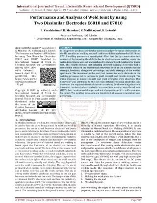
In this project we discussed the characteristics and performance of electrodes on the MS metal in arc welding method. In this two different electrodes E6010 and E7018 welding parameters investigated. After that the dye penetration test conducted for knowing the defects due to electrodes and welding ,again the welded specimens were cut and machined to standard configurations for tensile test. The results showed that selecting different welding electrodes had a remarkable effect on the mechanical properties such as the ultimate tensile strength, hardness, elongation percentage, and yield strength of the welded specimens. The increment in the electrical current for each electrode in the welding processes led to increase in yield strength and tensile strength. The initial increase in tensile strength and yield strengths were observed. This behaviour was attributed to the fact that different welding electrodes and increased the required electrical current to melting for the welding electrode, increased the electrical current led to increased heat input on heat affected zone HAZ , then the observed change mechanical properties which could create area for defect. The welding processes and tensile test at a room temperature was performed. P. Varalakshmi | K. Manohar | K. Mallikarjun | K. Lokesh "Performance and Analysis of Weld Joint by using Two Dissimilar Electrodes E6010 and E7018" Published in International Journal of Trend in Scientific Research and Development (ijtsrd), ISSN: 2456-6470, Volume-3 | Issue-3 , April 2019, URL: https://www.ijtsrd.com/papers/ijtsrd23172.pdf Paper URL: https://www.ijtsrd.com/engineering/manufacturing-engineering/23172/performance-and-analysis-of-weld-joint-by-using-two-dissimilar-electrodes-e6010-and-e7018/p-varalakshmi<br>

E N D
International Journal of Trend in Scientific Research and Development (IJTSRD) Volume: 3 | Issue: 3 | Mar-Apr 2019 Available Online: www.ijtsrd.com e-ISSN: 2456 - 6470 Performance and Analysis of Weld Joint by using Two Dissimilar Electrodes E6010 and E7018 P. Varalakshmi1, K. Manohar2, K. Mallikarjun2, K. Lokesh2 1Assistant Professor, 2UG Scholar 1,2Department of Mechanical Engineering, GNIT, Rangareddy, Telangana, India How to cite this paper: P. Varalakshmi | K. Manohar | K. Mallikarjun | K. Lokesh "Performance and Analysis of Weld Joint by using Two Dissimilar Electrodes E6010 and E7018" Published in International Journal of Trend in Scientific Research and Development (ijtsrd), ISSN: 2456- 6470, Volume-3 | Issue-3, April 2019, pp.919-923, URL: https://www.ijtsrd.c om/papers/ijtsrd23 172.pdf Copyright © 2019 by author(s) and International Journal of Trend in Scientific Research and Development Journal. This is an Open Access article distributed under the terms of the Creative Commons Attribution License (CC BY 4.0) (http://creativecommons.org/licenses/ by/4.0) 1.Introduction In shielded metal arc welding, the intense heat of electric arc is used to fuse the parts being joined. In most arc welding processes, the arc is struck between electrode and work piece, and is referred as direct arc. The arc is struck between non-consumable electrodes adjacent to parts being joined as indirect arc. In this case, the heat is transferred to metal by radiation. This method is rarely used because of low thermal efficiency. The principle of shielded metal arc welding is based upon the formation of an electric arc between electrode and base metal. The heat of the arc is concentrated at the point of welding, and as a result, it melts the electrode and base metal. When the weld metal solidifies, a joint is formed. When the metal solidifies, the slag gets deposited on its surface as it is lighter than metal, and the weld metal is allowed to cool gradually and slowly. The slag deposited over the weld is removed by chipping. The electric arc is produced when current flows across the air gap between the end of metal electrode and the work surface. This arc is strong stable electric discharge occurring in the air gap between an electrode and the work. The temperature of this arc is about 36000c which can melt and fuse the metal very quickly to produce joint. The temperature of the arc at the centre is around 65000c. Only 60 to 70 percent of the heat is utilised in shielded metal arc welding to heat up and melt the metal. The remaining heat is dissipated into surroundings. ABSTRACT In this project we discussed the characteristics and performance of electrodes on the MS metal in arc welding method. In this two different electrodes E6010 and E7018 welding parameters investigated. After that the dye penetration test conducted for knowing the defects due to electrodes and welding ,again the welded specimens were cut and machined to standard configurations for tensile test. The results showed that selecting different welding electrodes had a remarkable effect on the mechanical properties such as the ultimate tensile strength, hardness, elongation percentage, and yield strength of the welded specimens. The increment in the electrical current for each electrode in the welding processes led to increase in yield strength and tensile strength. The initial increase in tensile strength and yield strengths were observed. This behaviour was attributed to the fact that different welding electrodes and increased the required electrical current to melting for the welding electrode, increased the electrical current led to increased heat input on heat affected zone (HAZ), then the observed change mechanical properties which could create area for defect. The welding processes and tensile test at a room temperature was performed. IJTSRD23172 SMAW is the most common type of arc welding and it is normally a manual operation. Therefore, it is usually referred as Manual Metal Arc Welding (MMAW). It uses consumable metal electrodes. The composition of electrode is similar to that of the parent metal. When the bare electrode is used, the joint formed is weak and brittle. This is due to the absorption of oxygen and nitrogen from the atmosphere. To overcome these difficulties coated electrodes ae used. Flux coating on the electrode also melts and provides a gaseous shield around the arc which protects the molten pool from atmospheric contaminations. Electrode melts and provide filler metal for weld. The arc is produced with low voltage (20V-80V) but with very high current (80- 500 amps). The electric circuit consists AC or DC power source, and from the power source welding current is conveyed to work through electrode, electrode holder and welding leads. The sequences of steps involved in arc welding operation are: 1.Preparation of edges, 2.Holding the work piece in a fixture, 3.Striking the arc, and 4.Welding the joint. Before welding, the edges of the work pieces are suitably prepared, and the joint area is cleaned with the wire brush. @ IJTSRD | Unique Paper ID – IJTSRD23172 | Volume – 3 | Issue – 3 | Mar-Apr 2019 Page: 919
International Journal of Trend in Scientific Research and Development (IJTSRD) @ www.ijtsrd.com eISSN: 2456-6470 This ensures a joint. The parent metals are held in a fixture and welding leads are properly connected to power source. During the welding, the electrode is given the following motions. 1.The electrode is fed downwards, and it should be controlled properly to maintain constant gap (2 to 4mm). 2.The electrode is moved slowly along the joint. 3.The electrode tip is given an oscillating movement across the weld to maintain proper bead width and secure good penetration of the weld. The width of weave should not be greater than three times the diameter of the electrode. In multi pass welding, slag coated on the bead after the first pass should be chipped off and cleaned by wire brush before the start of the second pass. This procedure is followed for the subsequent passes. In most cases, after welding, the part must be heat-treated to change the size of the grain in the weld and the surrounding area. 1.1 SELECTION OF ELECTRODES Type of electrode used depends upon 1.The type of metal to be welded 2.The position in which the weld is to be done 3.The power source 4.Polarity, in case of D.C. 5.Thickness of the base metal 6.Expected properties of welded joint 2.EXPERIMENTAL WORK The material IS 2062 Grade B Mild Steel of the required dimension was purchased from the local market and the test specimen was prepared from it. The chemical composition of IS2062 Grade B mild steel by weight (wt %) is given as follow C-0.22, Mn1.50, Si-0.40, CE-0.41, P-0.045, S-0.045 and Fe. The test specimens for analysis of mechanical properties of hardness and tensile strength were prepared as per ASTM standard and its description is given below: Specimens for hardness test and tensile test and bending test: An impact test specimen as per ASTM A370 is prepared with the following dimensions. ?Length 150mm ?Width 150mm ?Thickness 8mm the grinding method. Initially the given specimen has unequal dimensions so for achieving the smooth specimen we have done the grinding around the specimen. At the top of the both specimens we remove some excess metal i.e,5mm and within angle of 33deg i.e., 66deg for two specimens. The main purpose of making angle is for achieving the ‘V’ with help of ‘V’ shape we have to maintain the cap during welding. Here we prepared the two work pieces simultaneously. Fig 2: After v groove preparation 2.1 Selection of particular type of groove geometry is influenced by following factors: ?Machining cost to obtain desired groove geometry ?Cost of weld metal (on the basis of volume) need to be deposited. ?Welding speed ?Accessibility of groove for depositing the weld metal. ?Residual stress and distortion control requirement. 2.2 V GROOVE SPECIFICATIONS ?Easier to obtain either by machining or flame cutting. ?Provide good accessibility for applying heat up to root of groove. ?Need to more volume of weld metal. 2.3 WELDING WITH E6010 ELECTRODE Earlier we discussed the during welding we have to maintain some constant gap between the two metal plates say (2 to 3mm). The welding can be done on both face and root of the metal plate. On the face layer, the welding can be done with two layers with two different diameters of electrode say 2.5mm and 3.15mm with different voltage, current. On the root layer, the welding can be done with only one layer with 3.15mm diameter electrode. The current and voltage of E6010 electrode during welding is on face layer for the layer 135V voltage and 75amps current and for layer 240V voltage and 90amps current. On the root layer, the current and voltage are 40V voltage and 90amps current. The maximum current for E6010 electrode is 40 to 180 amps. SELECTION OF SPECIFIC GROOVE Fig 1: Standard mild steel specimen Fig 3: Welding the work piece with E6010 2.4 WELDING WITH E7018 ELECTRODE The welding procedure is same as E6010 electrode metal but here we have to do the welding other work pieces with E7018 electrode. The current and voltage of E7018 electrode during welding is on face layer for the layer 120V voltage For every weld joint there is need to edge preparation, it provides the “good penetration” and “good strength” to the weld joint. In edge preparation the excess amount of material is removed along the edges of metal surface. The edge preparation and groove preparation are produced by @ IJTSRD | Unique Paper ID - IJTSRD23172 | Volume – 3 | Issue – 3 | Mar-Apr 2019 Page: 920
International Journal of Trend in Scientific Research and Development (IJTSRD) @ www.ijtsrd.com eISSN: 2456-6470 and 100amps current and for layer 2 25V voltage and 120amps current. On the root layer, the current and voltage are 22V voltage and 70amps current. The maximum current for E7018 electrode is 80 to 200 amps. Fig 6: Dye penetration liquid chemicals A.Pre-cleaning B.Application of penetrate C.Dwell time D.Excess removal of penetrate E.Application of developer F.Inspection G.Post cleaning A.Pre-cleaning It is the initial stage of the dye penetration test. In this the test surface is cleaned to remove dirt particles. Pre cleaning is necessary for all testing materials, because presence of dirt particles shows the false indications on the material. To avoid the false indications, it is required to all testing materials. For pre cleaning the alkaline solutions are generally used. Fig 4: Welding the work piece with E7018 2.5 The purpose of hardness test is the hardness of the parent metal and make an approximate determination of the materials tensile strength to assure the correct material is being welded. The hardness of the weld to ensure the weld metal meets or exceeds the strength requirements of the parent metal [1]. In our project, for testing the hardness values of weld joint we used the leeb hardness test for following reasons 1.It is a lighter, smaller and non-destructiveness device that leaves a little damage. 2.Speed, size and weight of the LHT make it easier to deal with in the field. 3.It provides accurate readings [2]. For testing the hardness of weld plate, we divided the plate as following manner A.Base metal B.Heat Affected zone area (HAZ) C.Welded area The hardness test procedure is same for both E6010 and E7018 electrode metals HARDNESS TEST Fig 7: Applying the pre cleaner on the specimen B.Application of penetrate The penetrant is then applied to the surface of the item being tested. The penetrant is usually a brilliant coloured mobile fluid with high wetting capability. Usually Di-methyl sulphoxides and azone are used as penetrates. Fig 5: Leeb hardness test machine 2.6 DYE PENETRATION TEST (DPT) It is a type of non-destructive test. The test is conducted for observing the surface defects on the weld metals. In dye penetration test we have applied some chemical agents in the sequential order as follows for both face layer and root layer. Fig 8: Application of penetrant @ IJTSRD | Unique Paper ID - IJTSRD23172 | Volume – 3 | Issue – 3 | Mar-Apr 2019 Page: 921
International Journal of Trend in Scientific Research and Development (IJTSRD) @ www.ijtsrd.com eISSN: 2456-6470 C.Dwell time Penetrant dwell time is the total time that the penetrant is in contact with the part surface. The dwell time is important because it allows the penetrant the time necessary to seep or be drawn into a defect. D.Excess removal penetrant The excess penetrant is then removed from the surface. Emulsifiers represent the highest sensitivity level, and chemically interact with the oily penetrant to make it removable with a water spray. If excess penetrant is not properly removed, once the developer is applied, it may leave a background in the developed area that can mask indications or defects. Fig 11: Identifying the defects for E6010 on face layer Fig 12: Identifying the defects for E6010 on root layer Fig 9: Excess removal penetrant E.Application of developer After excess penetrant has been removed, a white developer is applied to the sample. The AMS 2644 classify developers into six standard forms. These forms are listed below 1.Form a - Dry Powder 2.Form b - Water Soluble 3.Form c - Water Suspendable 4.Form d - Nonaqueous Type 1 Fluorescent (Solvent Based) 5.Form e - Nonaqueous Type 2 Visible Dye (Solvent Based) The developer draws penetrant from defects out onto the surface to form a visible indication, commonly known as bleed-out. Any areas that bleed out can indicate the location, orientation and possible types of defects on the surface. Fig 13: Identifying the defects for E7018 on face layer 2.7 It is a type of destructive test. By using tensile test, we have to find the tensile property of the weld joint. This test is conducted on the Universal Testing Machine (UTM). This test is conducted on both E6010 and E7018 electrode metal. TENSILE TEST Fig 14: Tensile test 2.8 It is also a type of destructive test. By using bending test, we have to find the maximum load bearing capacity of the weld joint. This test also conducted on the UTM. Bending test can be conducted on both root and face of the weld joint. BENDING TEST Fig 10: Application of developer F.Inspection In this step, we identify the defects occurs in weld joint with magnifying glasses. Inspection of the test surface should take place after 10- to 30-minute development time and is dependent on the penetrant and developer used. Fig 15: Bending test @ IJTSRD | Unique Paper ID - IJTSRD23172 | Volume – 3 | Issue – 3 | Mar-Apr 2019 Page: 922
International Journal of Trend in Scientific Research and Development (IJTSRD) @ www.ijtsrd.com eISSN: 2456-6470 3.RESULTS AND DISCUSSIONS 3.1 HARDNESS TEST RESULTS ON E6010 WELD METAL We get the following hardness values, while measuring the E6010 weld plate Table 1: Leeb Hardness Test values on E6010 weld metal Base metal (B1) Top 102 281 Middle 177 155 Bottom 163 244 3.2 HARDNESS TEST RESULTS ON E7018 WELD METAL We get the following hardness values, while measuring the E7018 weld plate Table 2: Leeb Hardness Test values on E6010 weld metal Base metal (B1) Top 344 367 Middle 376 378 Bottom 366 349 From above results we observed the hardness value of E6010 weld metal is lesser than E7018 weld metal. Here the E7018 weld metal has more indentation capacity than E6010 electrode metal. 4.RESULTS OF DYE PENETRATION TEST (DPT) By using DPT test we observed the following surface defects on E6010 weld metal. The defects as shown in figure 11 and figure 12. On face layer we observed the “Under cut” (UC) and “Poor start and stop” (PSS) defects as shown in figure 11. On root layer we observed the “Excess penetrate”(EP), “Under cut”(UC) and “Lack of fusion”(LF) defects as shown in figure 12. On E7018 weld metal we observing following defects as shown in figure 13. On face layer we observed the “Lack of penetration”(LF) and “Poor start and stop”(PSS) defects as shown in figure 13. On root layer we doesn’t have any defects any defects in the surface level, but the porosity defect occurs in the internal structure it can be observed by radiography test. From above results, we observed that E7018 weld metal has more strength than E6010 weld metal due to less effects. 5.RESULTS OF TENSILE TEST Tensile strength results on E6010 weld metal Load (KN) Deflection (mm) 112 Tensile strength results on E7018 weld metal Load (KN) Deflection (mm) 121 By observing the tensile test results, we concluded that E7018 weld metal has more tensile strength than E6010 weld metal. 6.RESULTS OF BENDING TEST We conducted the bending test on both E6010 and E7018 weld metal at both root and face of the weld metals. We got the following results in bending test. Bending test results for E6010 weld metal PositionLoad (KN) Deflection (mm) Face 20 Root 32 Bending test results for E7018 weld metal PositionLoad (KN) Deflection (mm) Face 75 Root 45 In this for root and face in E6010 electrode metal cracks occurs at weld joint. For E7018 there is no cracks are occurred for both root and face. With this result we concluded that the weld joint E7018 electrode metal has maximum load bearing capacity than E6010 electrode metal. The E7018 has more compressive strength than E6010 weld metal. 7.CONCLUSION After considering all parameters, shielded metal arc welding is a simple process which doesn’t need excessive amount of equipment. The tensile test, bending test, microstructure and hardness measurements are studied over two different electrodes on similar metals joined by shielded metal arc welding. Two similar metals are welded with different electrodes i.e. cellulosic and low hydrogen electrodes and examined. The present study can be concluded in the following steps: ?The value of tensile strength and hardness of the welded metal is higher when low hydrogen electrode is used as compared the case of cellulose electrodes. ?E6010 electrodes are intended for direct current (DC) only. Whereas E7018 electrodes are intended for alternating current (AC) and DC. ?E7018 electrodes also produce strong welds with high impact properties (even in cold weather) and can be used on carbon steel, high-carbon, low-alloy or high- strength steel base metals, due they contain a thick flux with high powder content. ?When low hydrogen (E7018) electrode is used, the root pass weld is smooth as compared to the cellulose (E6010) electrode with less slag [3]. REFERENCES [1]Aoki, H., & Matsukura, Y. (2007). A new technique for non-destructive field measurement of rock-surface strength: An application of the Equotip hardness tester to weathering studies. Earth Surface Processes and Landforms, 32, 1759–1769. doi:10.1002/esp.1492 Welded area (W1) 174 221 170 Base metal (B2) 303 272 269 HAZ (H1) HAZ (H2) Position 84 30 305 248 293 89 85 Welded area (W1) 356 436 343 Base metal (B2) 373 346 346 HAZ (H1) HAZ (H2) Position 443 465 377 23 [2]Welding handbook, Australian Welding Society, 1987, 8th edition, volume 1 & 2. [3]Impermeable Low Hydrogen Covered Electrodes: Weld Metal, Slag, and Fumes Evaluation Cláudio TuraniVaz, Alexandre QueirozBracarense, Ezequiel CairesPereira Pessoa in Material science and Technology (volume 1) September 2012. 39 IvanilzaFelizardo, @ IJTSRD | Unique Paper ID - IJTSRD23172 | Volume – 3 | Issue – 3 | Mar-Apr 2019 Page: 923