Download
1 / 6
60 likes | 76 Views
Chain hoist system play an important role in an industry to carry the load materials from one place to another. Computer aided design and analysis of chain hoist system is one of the techniques used in manufacturing sectors to arrive for the best manufacturing condition, which is an essential need for industry manufacturing of Chain Hoist at lower cost. The objective of this paper work is to study the design of various components which are used in chain hoist system. A sufficient amount of research work has been described by researchers on the modification of chain block system. In a vision of above, this paper work present a critical literature review on components design of hoisting mechanism of an EOT crane. Mr. Ankit P. Jaiswal | Prof. Kishor R. Sontakke "Design and Analysis of Chain Block System for Evaluation of Brake Load" Published in International Journal of Trend in Scientific Research and Development (ijtsrd), ISSN: 2456-6470, Volume-1 | Issue-6 , October 2017, URL: https://www.ijtsrd.com/papers/ijtsrd5819.pdf Paper URL: http://www.ijtsrd.com/engineering/mechanical-engineering/5819/design-and-analysis-of-chain-block-system-for-evaluation-of-brake-load/mr-ankit-p-jaiswal<br>

E N D
International Research Research and Development (IJTSRD) International Open Access Journal Design and Analysis of Chain Block System for Evaluation of Brake Load International Journal of Trend in Scientific Scientific (IJTSRD) International Open Access Journal ISSN No: 2456 ISSN No: 2456 - 6470 | www.ijtsrd.com | Volume 6470 | www.ijtsrd.com | Volume - 1 | Issue – 6 Design and Analysis of Chain Block System for Design and Analysis of Chain Block System for Evaluation of Brake Load Mr.Ankit P. Jaiswal Prof.Kishor R.Sontakke Associate Professor and HOD PLITMS, Mechanical Engg Department PLITMS, Buldanat Mechanical Engg Department PLITMS, Buldanat Prof.Kishor R.Sontakke Associate Professor and HOD PLITMS, M.E CAD/CAM Student, Mechanical Department PLITMS, Buldanat Department PLITMS, Buldanat M.E CAD/CAM Student, Mechanical Engg ABSTRACT of shape and materials of hooks enables the increase of loading capacity of hoisting machines. Need of the present day, equipment to handle heavy loads with fast speed, reliability, safety, economy etc. So the crane is used. Crane is one of the most import equipment used in the industries. It works as a material handling equipment or device. material handling equipment or device. of shape and materials of hooks enables the increase of loading capacity of hoisting machines. Need of the present day, equipment to handle heavy loads with fast speed, reliability, safety, economy etc. So the crane is used. Crane is one of the most important equipment used in the industries. It works as a Chain hoist system play an important role industry to carry the load/materials from one place to another. Computer aided design and analysis of chain hoist system is one of the techniques used in manufacturing sectors to arrive for the best manufacturing condition, which is an essential nee for industry manufacturing of Chain Hoist at lower cost. The objective of this paper work is to study the design of various components which are used in chain hoist system. A sufficient amount of research work has been described by researchers on the mod of chain block system. In a vision of above, this paper work present a critical literature review on components design of hoisting mechanism of an EOT crane play an important role in an industry to carry the load/materials from one place to another. Computer aided design and analysis of chain hoist system is one of the techniques used in manufacturing sectors to arrive for the best manufacturing condition, which is an essential need for industry manufacturing of Chain Hoist at lower cost. The objective of this paper work is to study the design of various components which are used in chain hoist system. A sufficient amount of research work has been described by researchers on the modification of chain block system. In a vision of above, this paper work present a critical literature review on components design of hoisting mechanism of an EOT Applications of material handling device is a prime consideration in the construction industry for the movement of material, in the manufacturing industry ssembling of heavy equipment, in the transport industry for the loading and unloading and in shipping etc. This device increase output, improves quality, speed up the deliveries and therefore, decrease the cost of production. The utility of this further been increased due to increase in labour costs and problems related to labour management. Crane is a combination of separate hoisting mechanism with a frame for lifting or a combination of lifting and moving load. There is very up a load at one point and be able to transport the object from one place to another place to increase human comfort. There are three major considerations in the design of cranes. First, the crane must be able to lift the weight of the load. Second, the rane must not topple. Third, the crane must not rupture. There are so many types of crane are available such as Tower crane, Truck mounted crane, EOT crane, Telescopic crane, Gantry crane, Aerial crane, stocker crane, etc. Here, discus about Electric ead Travelling (EOT) crane. EOT crane is also known as bridge crane. Electric Overhead cranes typically consist of either a single girder or a double Applications of material handling device is a prime consideration in the construction industry for the movement of material, in the manufacturing industry for the assembling of heavy equipment, in the transport industry for the loading and unloading and in shipping etc. This device increase output, improves quality, speed up the deliveries and therefore, decrease the cost of production. The utility of this device has further been increased due to increase in labour costs and problems related to labour management. Crane is a combination of separate hoisting mechanism with a frame for lifting or a combination of lifting and moving load. There is very much useful to pick up a load at one point and be able to transport the object from one place to another place to increase human comfort. There are three major considerations in the design of cranes. First, the crane must be able to lift the weight of the load. Second, the crane must not topple. Third, the crane must not rupture. There are so many types of crane are available such as Tower crane, Truck mounted crane, EOT crane, Telescopic crane, Gantry crane, Aerial crane, stocker crane, etc. Here, discus about Electric Overhead Travelling (EOT) crane. EOT crane is also known as bridge crane. Electric Overhead cranes typically consist of either a single girder or a double girder construction. Keywords: Crane hook, Wire rope, pulley and rope drum Crane hook, Wire rope, pulley and rope 1.INTRODUCTION A crane is hoisting device used for lifting or lowering load by means of a drum or lift wheel around which rope or chain wraps. EOT crane is a mechanical lifting device used for lifting or lowering the material and also used for moving the loads horizontally or vertically. It is useful when lifting or moving the loads is beyond the capacity of human. Crane is specially design structure equipped with mechanical means for a load by raising or lowering by electrical or manual operation. Cranes are commonly employed in the transport industry for loading and unloading of freight, in construction industry for the movement of materials; and in the manufacturing industry for the assembling of heavy equipment. Appropriate solution assembling of heavy equipment. Appropriate solution vice used for lifting or lowering load by means of a drum or lift wheel around which rope or chain wraps. EOT crane is a mechanical lifting device used for lifting or lowering the material and also used for moving the loads horizontally or s useful when lifting or moving the loads is beyond the capacity of human. Crane is specially design structure equipped with mechanical means for a load by raising or lowering by electrical or manual operation. Cranes are commonly employed in the industry for loading and unloading of freight, in construction industry for the movement of materials; and in the manufacturing industry for the @ IJTSRD | Available Online @ www.ijtsrd.com @ IJTSRD | Available Online @ www.ijtsrd.com | Volume – 1 | Issue – 6 | Sep - Oct 2017 Oct 2017 Page: 1237
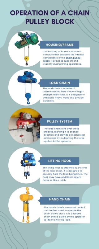
International Journal of Trend in Scientific Research and Development (IJTSRD) ISSN: 2456-6470 1.2. Types of Overhead Cranes Various types of overhead cranes are used in industries with many being highly specialized. Various types of overhead cranes are single girder cranes, double girder cranes, gantry cranes and monorails. a.Single Girder Cranes The crane consists of a single bridge girder supported on two end trucks. It has a trolley hoist mechanism that runs on the bottom flange of the bridge girder. Fig. 1: Schematic view of the hoisting device b.Double Girder Cranes The crane consists of two bridge girders supported on two end trucks (end carriages). The trolley runs on rails on the top of the bridge girders. Double girder electric overhead cranes are widely used in the industries because they can carry more loads with more span than any other type of crane. In this project we are concentrating mainly on double girder electric overhead cranes. 2.LITERATURE REVIEW For the development of the new technique, operation, process or methodology it is very important to make detail study on the existing techniques, operation, process or methodology and to understand the same for elimination of problems concerned with them. So with the objective of achieving a fuller understanding of this technology, an interest has been taken to finding out the suitable material foe design the pulley and chain link rather than the existing one. The following are the some design modification is carried out on the EOT. c.Gantry Cranes These cranes are essentially the same as the regular overhead cranes except that the bridge for carrying the trolley or trolleys is rigidly supported on two or more legs. Y. Torres et. [1], initially studied the probable causes of failure of crane hook. It includes the manufacturing and lifting of crane hook, experimental analysis mechanical behaviour of material of crane hook. It was concluded that the brittle fracture was originate from crack in the material. 1.3. Parts of the Hoisting Devices A hoisting device is used for lifting or lowering a load by means of a drum or lift-wheel around which rope or chain wraps. It may be manually operated, electrically or pneumatically driven and may use chain, fiber or wire rope as its lifting medium E. Narvydas et. al [2], investigated circumferential stress concentration factors with shallow notches of the lifting hooks of trapezoidal cross-section employing finite element analysis (FEA).The stress concentration factors were widely used in strength and durability evaluation of structures and machine elements. The FEA results were used and fitted with selected generic equation.This yields formulas for the fast engineering evaluation of stress concentration factors without the usage of finite element models.The design rules of the lifting hooks require using ductile materials to avoid brittle failure; in this respect they investigated the strain,based criteria for failure, accounting the stress variations. e.g.: Elevators, crane Here the hoisting part of an EOT crane is discussed The hoisting part of the EOT crane consists of the following parts Hoist motor Gear box Drum Pulleys Wire rope Hook Rashmi Uddanwadiker[3], studied stress analysis of crane hook using finite element method and validated results using Photo elasticity. Photo elasticity test is based on the property of birefringence. To study stress pattern in the hook in a loaded condition analysis was @ IJTSRD | Available Online @ www.ijtsrd.com | Volume – 1 | Issue – 6 | Sep - Oct 2017 Page: 1238
International Journal of Trend in Scientific Research and Development (IJTSRD) ISSN: 2456-6470 carried out in two steps firstly by FEM stress analysis of approximate model and results were validated against photo elastic experiment. Secondly, assuming hook as a curved beam and its verification using FEM of exact hook. The ANSYS results were compared with analytical calculations, the results were found in agreement with a small percentage error = 8.26%. Based on the stress concentration area, the shape modifications were introduced in order to increase strength of the hook. c.Breaking Strength of Chain Link No. of rope parts (nt) = 1 Efficiency of pulley or drum (p) = 94% From Design Data Book, for n =11, 5000 ??х???.?? ?ℎ??? ????= 5319? ? = d.Selecting the Chain Link Spasoje Trifkovic et. al [4], this paper analyzes the stress state in the hook using approximate and exact methods. They calculated stresses in various parts of the hook material firstly by assuming hook as a straight beam and then assuming it as curved beam Analytical methods were used with the help of computers, using FEM. Now, ? ? ? = ? ?? ??−(?? − ??) ???? Where, Bernard Ross et. al [5], this paper describes the comprehensive engineering analysis of the crane accident, Under taken to disprove the Mitsubishi theories of failure as confirmed by jury verdict. Crucial role of the SAE J1093, 2% design side load criterion and Lampson’s justification or an 85% crawler crane stability criterion were presented. ??= Tensile of the wire = 1600 N / mm2 ?? = Design factor = 4 E r = Corrected modulus of elasticity D = Diameter of drum d = Diameter of Chain link 3.DESIGN COMPONENT CALCULATION OF CRANE P = Breaking strength of Chain Link = 5319N Now, all values are put in this equation, A = 30.39mm2 A 0.4d 2 3.1 Selection of Material The selection of material is very important thing in order to design any mechanical components. The recent trends towards optimizing the mechanical components through continuous design modification needs lots of data to maintained, also during the design proper material selection is also needed. The presented design of drum and chain link for EOT crane described with used of two different material like SAE 1041 and glass fiber is used. The basic mechanical properties of the materials as shown in the following table 4.1 and 4.2 d 8mm e.Design of Pulley or Hoisting Drum Hoisting drum with one coiling rope has only one helix, while the drums with two coiling ropes are provided with helices, right hand & left hand. A design procedure of hoisting drum is as under: Minimum diameter of pulley = 16d = 128mm It is advisable to take diameter of pulley = 27d = 216mm 3.2 Basic Calculation of EOT Crane a.Total Lifting Capacity (W) = 0.5 ton Diameter of compensating pulleys = 0.5 X 10000 N D1= 0.6x 216 =129.6mm, D1=130mm = 5000 N a) Number of turns on a drum for one rope member b.Lifting Height = 29.95 meter = 29.95 X 1000 ? = ??? 22 ????? ????∗? ?.??∗???? + 2=21.10 turns≅ ??? + 2 = ? = 29950 mm @ IJTSRD | Available Online @ www.ijtsrd.com | Volume – 1 | Issue – 6 | Sep - Oct 2017 Page: 1239
International Journal of Trend in Scientific Research and Development (IJTSRD) ISSN: 2456-6470 Where, h = height of load to which it is raised (Consider double of height) IV. Total normal stress on drum ??= ?(??? − ???) = ?(14.90?− 37?)=39.88 ?/ ??? i = ratio of pulley system = 2 D = drum diameter = 25d = 25(8) = 200 mm (Permissible bending stress is 20 MPa) b) Length of Drum ? = ??2ℎ? 4.APPROACH FOR MODELING Modeling of Drum and Chain Link ??? + 7? ∗ ?? The drum is model with the below rated parameter ? = ??2 ∗ 6000 ∗ 2 3.14 ∗ 200? + 7? ∗ 9.5 = 430?? Table:1. Summaries of Dimension Diameter of Drum (D) 248 mm p = pitch of grooves of two turn = 9.5mm Inner Diameter of Drum (H) 172 mm c) Thickness of Drum Thickness 14 mm ? = 0.02? + 10 = 14?? d) Outer diameter of drum Diameter of Chain Link 8mm ??= ? + 6? = 248?? e) Inner diameter of drum ??= ? − 2? = 172?? f) Checking for the stresses in the drum I. Compressive stress in the drum ? 5000 14 ∗ 9.537?/??? ??= ?(??) ??? = II. Maximum bending stress 8??? (??− ??)? ??? ??= Figure 2: 3D model of Drum or Pulley ??=8 ∗ 5000 ∗ 430 ∗ 200 (200?− 172?) ∗ 3.14 ??? = 14.90?/??? III. Maximum shear stress 16????? (??− ??)? ??? =16 ∗ 553176 ∗ 200 ? ??? ? = ∗ 3.14 (200?− 172?) = 7.66 Figure 3: Equivalent Stress of drum in ANSYS @ IJTSRD | Available Online @ www.ijtsrd.com | Volume – 1 | Issue – 6 | Sep - Oct 2017 Page: 1240
International Journal of Trend in Scientific Research and Development (IJTSRD) ISSN: 2456-6470 structure can be analysed for its ultimate load by any of the following methods: (1) static method, (2) kinematics method. First of all analytical calculation of 0.5 ton crane and derived stresses and deformation, here we compare with software and analytically solutions. 1) Comparison of analytical and software analyzed values of equivalent stress when load lift, at mid point analytically 37 N/mm2 and software 30.957 N/mm2 for the drum. Fig.4. Total Deformation stress on chain link 2) The equivalent stress in the case of drum with SAE 1045 and SAE 1018, material found to be near about same.i.e.30.95. Table 2: Summaries of results obtained from Computational and Analytical Calculations 3) The maximum deformation or drum is maximum for the SAE 1045 compared with SAE 1018 at the maximum loading conditions. For Drum Properties SAE 1045 SAE 1018 Analytical Treat 4) The results obtained analytical and computationally for chain link shows good match between together. Equivalent Stress (Mpa) 5) For maximum load of 5000N the chain equivalent stresses distribution nearly equal for SAE 1045 and SAE1018. 30.957 30.95 37.28 Total Deformation (mm) 6) As same as drum the deformation is varies slightly in the case of chain link. The maximum deformation for SAE 1018 is maximum than SAE 1045. 0.008397 0.008354 0.0072 7) The comparative study shows that, during manufacturing or design the SAE 1045 is suitable for design the drum or pulley, while the chain link is suitable to design with 1018. For Chain Link Equivalent Stress (Mpa) 36.492 35.89 --- Acknowledgments The author gratefully acknowledges for the valuable suggestion by Prof.K.R.Sontakke Professor and Dean.-Mechanical Engineering) and also by Prof. S. J. Parihar(Assistant Professor and HOD-Mechanical Engg.) and special thanks Dr. P. M. Jawandhiya (Principal) for their extreme support to complete this assignment. Total Deformation (mm) 0.0007628 0.0009026 --- (Associate CONCLUSION This study investigated the elements that contribute to design and analysis of drum and chain link of EOT Crain. In this research work the analytical and computational analysis of is carried out for load of 5000N. The drum and chain link of EOT is designed by using Pro-E software. The structural feasibility is analyzed by Finite Element Analysis method. Finite Element Analysis is used in this project. Finite Element Analysis method is used to obtain the maximum deformation and stress experienced by the drum and chain link with loading of 5000N. REFERENCES 1)Mr. A. Gopichand, Ms. R. V. S. Lakshmi, Mr. B. Maheshkrishna “Optimization of design parameter for crane hook using taguchi method” in international journals of innovative research in science ,engineering and technology, vol. 2, Dec 2013, ISSN: 2319-8753. 2)Chetan N. Benkar, Dr. N. A. Wankhade “Finite Element stress Analysis of Crane With Different Cross Sections” in International Journal For Technological Hook By implementation of using the principle of virtual work and upper and lower bound theorems, a Research In @ IJTSRD | Available Online @ www.ijtsrd.com | Volume – 1 | Issue – 6 | Sep - Oct 2017 Page: 1241
International Journal of Trend in Scientific Research and Development (IJTSRD) ISSN: 2456-6470 6)Yogi Raval, “Design analysis and improvement of EOT crane wheel”, science technology & engineering, ISSN: 2349- 784X, Volume 1, Issue 11, May 2015. 7)Abhinay Suratkar and Vishal Shukla, “3D Modelling and finite element analysis of EOT crane”, International Journal of mechanical and production engineering, ISSN:2320-2092, Volume-1, Issue 2, Aug2013. 8)Patel P. and Nirav K, “Design and analysis of major components of 120 Tones capacity of EOT crane”, IJEDR 2014, ISSN: 2321-9939, volume-2, issue 2. 9)Prof. V.K.Jani and Apeksha Patel, “Design and Dynamic analysis of 70T double girder overhead crane”, ISSN: 0975-668X, Nov-12 to Oct-13, Volume-2, 10)N. Rudenko, Material Handling Equipment, 2nd edition, Envee Publishers, New Delhi. Engineering, volume 1, Issue 9,May-2014, ISSN 2347- 4718. 3)M. Shaban, M. I. Mohamed, A. E. Abuelezz and T. Khalifa,“Determination Of Distribution in Crane Hook by Caustic” in International Journal of Innovative Research in science, Engineering and Technology, Vol. 2 Issue 5, May 2013, ISSN: 2319-8753. 4)Apeksha. K. Patel, Prof. V. K. Jani, “Design and Dynamic Analysis of 70T Electrical Overhead Crane” in Journal of Information, Knowledge and Mechanical Engineering Vol.2, Oct-2013, ISSN- 975-668X. 5)Pradyumna kesharimaharana, “Computer Aided Analysis and Design of Hoisting Mechanism an EOT Crane”, .Thesis, National Institute of Technology Rourkela, May-2012. International Journal of Stress Double Girder Research in electric of and Issue 2. @ IJTSRD | Available Online @ www.ijtsrd.com | Volume – 1 | Issue – 6 | Sep - Oct 2017 Page: 1242