Download
1 / 15
150 likes | 270 Views
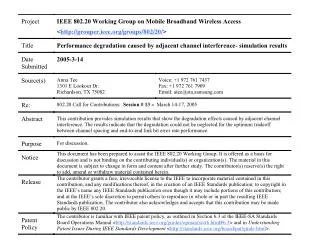
This study simulates various block assignments and evaluates the performance of multiple carriers in a channel block, focusing on 802.20 evaluation criteria. It analyzes the impact of adjacent channel interference (ACI) on system performance, particularly how channel spacing affects spectral efficiency and error rates. By utilizing a power amplifier model, the research identifies the trade-offs in spacing configurations while highlighting degradation thresholds. Results suggest adopting unified methodologies for evaluating non-linearities and ACI, ensuring fair technology comparisons in wireless communication systems.

E N D
Simulation and Evaluation of Various Block Assignments • Evaluation of multiple carriers deployed in a channel block • 802.20 evaluation criteria section 16 stated the channel block size to be evaluated: • 2 x 5 MHz (total 10 MHz) • 2 x 15 MHz (total 30 MHz) • For example, if a proposed technology is designed for a channel bandwidth that is significantly smaller than the channel block size in the evaluation, a few carriers may be placed adjacent to each other so as to increase the spectral efficiency for the evaluated block size. • In addition to the requirement to meet the FCC out-of-band spectral emission at the block edges, the adjacent channel interference may cause a performance degradation, depending on the channel spacing
Adjacent Channel Interference • Depending on the technology design, different levels of adjacent channel interference can be tolerated with performance degradation • The more adjacent channels are packed into the channel block, the higher the spectral efficiency, provided that the performance degradation can be tolerated in the system link budget • A tradeoff exists between channel spacing and performance degradation caused by adjacent channel interference • Another important factor causing adjacent channel interference is the spectral re-growth caused by the power amplifier (PA) non-linearity • Amount of spectral re-growth and thus adjacent channel interference depends on: • signal waveform, e.g., (99.99%) peak to average power ratio • Power amplifier characteristics and the operating point
Simulation Model • A similar simulation model has been discussed in Contribution C802.20-04/68r1 • 3 adjacent channels are modeled with the desired channel in the center • Adjacent channels transmit random data using the same technology • Signals from all 3 channels are combined and passed through a single PA • Simulation was repeated for a few values of channel spacing • End-to-end link performance measured in terms of probability of bit error • Both uncoded and coded cases are simulated
Power amplifier model • The PA model used in this simulation is RAPP’s model for the AM/AM characteristics: • Model parameter p = 2 • Operating point of PA selected such that the Output Backoff is about 5 dB
Power spectrum of transmitted signal - wide channel spacing • 3 adjacent channel with channel spacing ~ 1.388 x Channel Bandwidth
Power spectrum of transmitted signal - narrow channel spacing • 3 adjacent channel with channel spacing ~ 0.992 x Channel Bandwidth
Simulation results – Uncoded case • Channel spacing at Df, 0.92 Df, 0.88 Df, 0.82 Df and 0.8 Df • Df = Channel Bandwidth • Error floor appears for channel spacing < 0.82 Df
Simulation results – Coded case • R-1/2 convolutional code • Channel spacing at Df, 0.92 Df, 0.88 Df, 0.82 Df and 0.8 Df • Error floor significantly reduced, e.g., with 0.82 Df, degradation ~ 0.5 dB at BER ~ 10-4
Performance degradation caused by adjacent channel interference • Based on the simulation results in this example • If channel spacing is set to 0.88 Df, there is no performance degradation in BER performance caused by the adjacent channel interference • But, if the channel spacing is 0.82 Df, there is an associated performance degradation • Even worse, if channel spacing is 0.8 Df, degradation at 10-4 BER is ~ 2 dB • Better spectral efficiency may be achieved in the second case, but the performance degradation will need to be taken into account in technology evaluation, e.g., • 0.5 dB degradation at 10-4 BER, 0.8 dB degradation at 10-5 BER… • Tradeoff scenario depends on the system design and parameters: • Signal waveform characteristics • Coding rate • PA characteristics
Recommendations • Option 1: • For the purpose of proposal evaluation to enable fair comparison between technology, adopt a common non-linearity model and methodology for simulating the effects of adjacent channel interference • For example, adopt proposed text in C802.20-04/68r1 and, • Replace Figure 1 by the revised simulation model in slide 5 • Replace Figure 2 PA model by RAPP’s model as shown in slide 6 • Refine the proposed text
Option 1 x.x. Link level simulation model to include the effects of adjacent channel interference When multiple frequency channels are deployed in an assigned channel block, the effect of adjacent channel interference (ACI) can be modeled and included in the link level simulation as shown in Figure 1. A non-linearity model that can be used in the simulation is shown in Figure 2 [TBD]. Link performance of the desired user under the effect of ACI can be obtained through the computation of error probabilities at the receiver. The result of link performance should then be incorporated into the system level simulation. The desired signal is generated by the transmitter model with carrier frequency at fc. Two interfering signals, which are generated by similar transmitter models, each of which represents an adjacent channel centered at Df on each side of the desired channel that is centered about fc. Df is the required channel spacing for the specific proposed technology. A typical and the worst case scenarios should both be evaluated. The typical scenario is the one in which all three channels are transmitting at the same power. The worst case scenario happens when the adjacent channels are transmitting at their maximum power, while the desired channel is transmitting at the minimum power. The set of link-level simulation results that need to be incorporated into the system simulation should reflect the performance degradation caused by ACI, based on this simulation methodology. For the channels that are located at the two edges of a frequency block, interference from only one adjacent channel needs to be considered.
Recommendation – Option 2 • Option 2: • Include the following statement in Section 16 of the Evaluation Criteria Document V.14:- • In addition, the performance degradation associated with the adjacent channel interference needs to be stated and included in the system level evaluation. • - Placed at the end of the following paragraph in the current text: • “A proposal should specify the channel spacing …out-of-band emission limits”
References • IEEE 802.20 Evaluation Criteria document, V. 14, March 2005 • “Evaluation of 802.20 proposals with adjacent channel interference considerations – Description text”, C802.20-04/68r1, September 2004 • “Models for signal clipping in evaluation of MBWA”, C802.20-04/83, Sept. 2004 • “Method for capturing noises in digital receiver”, C802.20-04/81, Nov. 2004 • “Proposed text for methodology for capturing noise in digital receivers”, C802.20/89r1, January 2005.