Download
1 / 2
20 likes | 64 Views
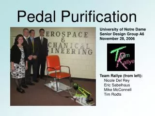
Due to industrial development, use of natural fuel is increasing continuously that's why there is need of alternating source of senergy. Eg Human energy. To reduce use of natural fuel we can use bicycle technology to run a machine using human power. Dynapods Greek word for power and foot. Dynapods can be run by one or two person. We are transmitting rotary motion from paddle to wheel of mill. Human input is low as compare to hand operated machine Dr. Kishorkumar Guru | Saurabh Pratap Singh | Saurabh Tiwari | Saurabh Pal | Saurabh Kumar Shukla "Design and Working of Pedal Operated Flour Mill" Published in International Journal of Trend in Scientific Research and Development (ijtsrd), ISSN: 2456-6470, Volume-3 | Issue-3 , April 2019, URL: https://www.ijtsrd.com/papers/ijtsrd23297.pdf Paper URL: https://www.ijtsrd.com/engineering/mechanical-engineering/23297/design-and-working-of-pedal-operated-flour-mill/dr-kishorkumar-guru<br>

E N D
International Journal of Trend in Scientific Research and Development (IJTSRD) Volume: 3 | Issue: 3 | Mar-Apr 2019 Available Online: www.ijtsrd.com e-ISSN: 2456 - 6470 Design and Working of Pedal Operated Flour Mill Dr. Kishorkumar Guru1, Saurabh Pratap Singh2, Saurabh Tiwari2, Saurabh Pal2, Saurabh Kumar Shukla2 1Sr. Professor, 2Student 1,2Department of Mechanical Engineering, ABES Engineering College, Ghaziabad, Uttar Pradesh, India to cite this paper: Dr. Kishorkumar Guru | Saurabh Pratap Singh | Saurabh Tiwari | Saurabh Pal | Saurabh Kumar Shukla "Design and Working of Pedal Operated Flour Mill" Published in International Journal of Trend in Scientific Research and Development (ijtsrd), ISSN: 2456- 6470, Volume-3 | Issue-3, April 2019, pp.1279--1280, URL: https://www.ijtsrd.c om/papers/ijtsrd23 297.pdf Copyright © 2019 by author(s) and International Journal of Trend in Scientific Research and Development Journal. This is an Open Access article distributed under the terms of the Creative Commons Attribution License (CC BY 4.0) (http://creativecommons.org/licenses/ by/4.0) Introduction Keeping these limitations of human capabilities in mind the proposed machine consists of three sub systems: 1.The energy unit, 2.Transmission mechanism 3.The process unit. Paddling power= 4X handling power If it will be run by ¼ horse power then a person can work for 10 minutes. If it will be run by 1/8 horse power then a person can work for 60 minutes. 94Watt(.12HP) can be maintained for 60 minutes or more. DESIGN Pedal Power T= 7X9.81X170 =11673.9Nmm =11.6739Nm Power= (2X3.14X70X11.6739)/60 =85.53W Na=70rpm Ta=44 Nb=? Tb=18 Na/Nb = Tb/Ta =18/44 =0.409 Nb=171.11rpm How ABSTRACT Due to industrial development, use of natural fuel is increasing continuously that’s why there is need of alternating source of senergy. Eg Human energy. To reduce use of natural fuel we can use bicycle technology to run a machine using human power. Dynapods ( Greek word) for power and foot. Dynapods can be run by one or two person. We are transmitting rotary motion from paddle to wheel of mill. Human input is low as compare to hand operated machine Keywords: industrial devlopement, energy, human energy, bicycle technology, dynapods, rotary motio , pedal operated machine, natural fuel etc IJTSRD23297 Wheel Design Of Mill Diameter of cycle’s wheel=50.8cm Diameter of mill’s wheel =22cm Nc=Nb=171.11rpm Nc/Nd=Db/Dc=50.8/22 Nd=395.10rpm DESIGN OF CHAIN Pitch of chain =[2X3.14(Ra+Rb)]/(Ta+Tb) =[2X3.14X(100+45)]/(44+18) =14.68mm Design of V belt It depends on speed of driving and driven Power Center Distance Speed ratio Service Condition Speed Ratio=Nd/Nc=395.1/171.11=2.309 According to this speed ratio Diameter Factor =1.13(Design data book) Equibalent dia=220X1.13=248.6mm Based on this we select belt cross section V=3.14XDdXNd/60= 3.14X220X395.1/60 =4.548m/sec @ IJTSRD | Unique Paper ID – IJTSRD23297 | Volume – 3 | Issue – 3 | Mar-Apr 2019 Page: 1279
International Journal of Trend in Scientific Research and Development (IJTSRD) @ www.ijtsrd.com eISSN: 2456-6470 Power transmission capacity N*=v(1.47/v0.09-143.27/De-2.34v2/104) =3.1917KW Based on these factor V belt of ‘C’ type. Upper width=22mm Thickness=14mm T=torque Na=rotational speed of larger spoket Nb= rotational speed of smaller spoket Nc= rotational speed of rare wheel Nd= rotational speed of wheel of mill Ta=teeth on larger spoket Tb= teeth on smaller spoket Working concept and Model In conventional stone wheel mechanism the intermittent flow is required to get fine output. The same type of arrangements of flow is made in Pedal operated flour mill. It consists of Hopper mechanism in which the grains are stored. It is having a flow control unit, which is connected by means of mechanical spring to the left hand brakes. By breaking, the flow may control. The output of the stone wheel mechanism is collected between a hemispherical collector which is located below the stone wheel mechanism. The energy unit basically consists of conventional bicycle mechanism; the transmission mechanism consists of chain drive running over a pair of sprockets and belt drive running over pulley and stone wheels The process unit is a pair of stone wheels mounted over one another where the wheat gets crushed into powered form to produce wheat flour. All these units are assembled on bicycle like structure ( seat , saddle, handle etc). Drive unit: This is first stage of transmission. The transmission of power from human to processing unit is carried out in two stages namely chain drive and belt drive. The operators uses his feet & legs to rotate pedal around the crank axel. 1-Front Chain Sprocket, 2-Pedal ,3-Chain ,4-Rear chain sprocket 5-Bearings for belt drive shaft , 7-CrossV Belt, 8- Stonewheels Refrences [1]Prasad A. Hatwalne, Sushil T. Ambadkar, R.V.Paropate, Vivek R. Gandhewar, A. M. Wankhade “Design and development of Pedal operated flour mill.” New York Science Journal, 2011; [2]P.B. Khope, J. P Modak “Development and Performance Evaluation of a Human Powered Flywheel Motor Operated Forge Cutter.” international journal of scientific & technology research volume 2, issue 3, March 2013. [3]Design Data , Data book of Engineers, (ISBN 978-81- 927355-0-4, Compiled by PSG College of Engineering and Published by Kalaikathir Achchagam, Coimbatore, India) [4]International Journal of Latest Engineering and Management Research (IJLEMR) ISSN: 2455-4847 [5] H. J. Hopfen (1969): Farm Implements for Arid and Tropical Regions Published by Food and Agriculture Organization of the United Nations, Via delle Terme di Caracalla 00100 Rome, Italy. Published in AT Microfiche Reference Library, pp.150 [6] David Gordon Wilson (1986): Understanding Pedal Power, A Technical Paper-51, Published in Volunteers in Technical Assistance, ISBN: 0-86619-268-9 @ IJTSRD | Unique Paper ID – IJTSRD23297 | Volume – 3 | Issue – 3 | Mar-Apr 2019 Page: 1280