Download
1 / 4
40 likes | 64 Views
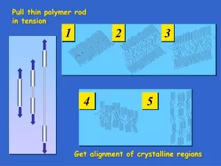
The main criterion of this project is to design a suspension system practically to a student formula vehicle and for systems, now loads are distributed to front and rear side. The stiffness of the spring is calculated by considering front and rear loads. The design of the spring, dash pot, rocker arms and push rod were done by LOTUS SHARK and modelling of these is done in SOLIDWORKS software. Later, the assembly of all parts and mono spring rocker arm front suspension system were designed racing cars. The dynamic loads are to be considered for the design of wheel assembly, frame, and transmission, steering and braking. Sateesh Kumar Revoor | Mittapally Nikhil | Jatothu Sucharitha | D. Anil "Design and Modeling of Pull Rod & Push Rod Suspension System" Published in International Journal of Trend in Scientific Research and Development (ijtsrd), ISSN: 2456-6470, Volume-3 | Issue-3 , April 2019, URL: https://www.ijtsrd.com/papers/ijtsrd23263.pdf Paper URL: https://www.ijtsrd.com/engineering/mechanical-engineering/23263/design-and-modeling-of-pull-rod-and-push-rod-suspension-system/sateesh-kumar-revoor<br>

E N D
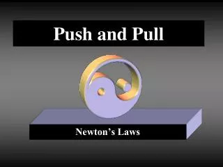
International Journal of Trend in Scientific Research and Development (IJTSRD) Volume: 3 | Issue: 3 | Mar-Apr 2019 Available Online: www.ijtsrd.com e-ISSN: 2456 - 6470 Design and Modeling of Pull Rod & Push Rod Suspension System Sateesh Kumar Revoor1, Mittapally Nikhil2, Jatothu Sucharitha2, D. Anil2 1Assistant Professor, 2Student 1,2Mechanical Department, GNIT Guru Nanak Institute of Technology, Hyderabad, India How to cite this paper: Sateesh Kumar Revoor | Mittapally Nikhil | Jatothu Sucharitha | D. Anil "Design and Modeling of Pull Rod & Push Rod Suspension System" Published in International Journal of Trend in Scientific Research and Development (ijtsrd), ISSN: 2456- 6470, Volume-3 | Issue-3, April 2019, pp.1074-1077, URL: https://www.ijtsrd.c om/papers/ijtsrd23 263.pdf Copyright © 2019 by author(s) and International Journal of Trend in Scientific Research and Development Journal. This is an Open Access article distributed under the terms of the Creative Commons Attribution License (CC BY 4.0) (http://creativecommons.org/licenses/ by/4.0) I. Introduction ABSTRACT The main criterion of this project is to design a suspension system practically to a student formula vehicle and for systems, now loads are distributed to front and rear side. The stiffness of the spring is calculated by considering front and rear loads. The design of the spring, dash pot, rocker arms and push rod were done by LOTUS SHARK and modelling of these is done in SOLIDWORKS software. Later, the assembly of all parts and mono spring rocker arm front suspension system were designed racing cars. The dynamic loads are to be considered for the design of wheel assembly, frame, and transmission, steering and braking. Keywords: Rocker Arm, Dash Pot, Push rod and Pull rod and Lotus Shark IJTSRD23263 1.Push Rod In push rod suspension arm as shown in Fig.1. is usually at a 45 degree angle the bodywork/tyre in an F1 car. When the car goes over a bump the movement is transffered throuh the tyre and rim to the suspension arm, this then transfer the loads into the “actual” suspension [1]. 2.Pull Rod Pull-rod suspension as shown in Fig.1. is literally just push- rod turned upside down, they take all the internal suspension parts and flip them upside down, then mount them as low in the chasis as possible to help witrh centre of gravity. This also means that the suspension arm as shown in Fig.2. can be mounted down near horizontal with respect to the road which is much better aerodynamically [2]. II. DESIGN OF PULL PUSH ROD SUSPENSION 1.LOTUS SHARK SUSPENSION DESIGN Fig.1. Front View of Pull or Push Rod Suspension Fig.2. Rocker Arm Fig.3. Suspension Design in Lotus Shark @ IJTSRD | Unique Paper ID – IJTSRD23263 | Volume – 3 | Issue – 3 | Mar-Apr 2019 Page: 1074
International Journal of Trend in Scientific Research and Development (IJTSRD) @ www.ijtsrd.com eISSN: 2456-6470 A market leading application for suspension modelling and design as shown in Fig.3. from the world-leaders in vehicle ride and handling; the lotus suspension analysis SHARK module is a suspension geometric and kinematic modelling tool, with a user- friendly interface which makes it easy to apply changes to proposed geometry and instantaneously assess their impact trough the graphical results as shown in Fig.4, Fig.5 and Fig.6. 2.1 Design of spring Design Considerations Spring Material: Stain less steel Larger diameter D=50mm Minor diameter (or) wire diameter d = 6mm Material properties Ultimate strength=505Mpa Modulus of elasticity=193Gpa Poisson ratio=0.29 Shear modulus=77Gpa Out side diameter of a spring D1=D+d =50+6 = 56 Inner diameter of a spring D2=D-d =50-6 =44 Spring index C = Calculation of Spring Fig.4. Camber Graph = Correction Factor = 8.3333 Kw= =1.1773039 Maximum shear stress in the spring wire + = F = 856.278 ≈ 900 N Stiffness factor Fig.5. Caster Graph K=21.40625 N/mm No. of turns of coil N = 6.731 ≈ 7 no. Damper travel = 50mm Modeling of spring designed as shown in Fig.7. according the above calculations. And fabricated by the cold drawn process and assembled to the dash pot. Fig.6. King-Pin Inclination 2.Solid Works for Modeling 3D model of suspension components in modeling software’s, we used SOLIDFWORKS for modeling of componenets. The 3D coordinate hard points are drawn from the suspensiuon software called LOTUS SHARK. Next the reference plane on which the sketch will be applied according to modeling tools required to model. Finallythe parameters of the sketch such as number of iterations and suppressed occurrences are defined. In modeling the suspension system components Fig.7. Spring And Dashpot Assembly @ IJTSRD | Unique Paper ID - IJTSRD23263 | Volume – 3 | Issue – 3 | Mar-Apr 2019 Page: 1075
International Journal of Trend in Scientific Research and Development (IJTSRD) @ www.ijtsrd.com eISSN: 2456-6470 Rocker Arm Rocker arm is a kinematic link which varies the motion according to the motion ratio required for the suspension. Dcesigns of rocker arm, thed inputs are drawn from the software. Modeling of rocker are designed in solid works as shown in Fig.8 and Fig.9. by using the specific tools for modeling. Considering the material for the rocker is stainless steel. And fabricated by using the TIG welding process according the design. Fig.10. Front View of Pushrod Suspension Fig.8. Free Body Diagram of Rocker Arm Fig.11. Iso Metric View of Pushrod Suspension Fig.12. Side View of Pushrod Suspension Fig.9. Rocker Arm Design Assembly An assembly is a model comprised of multiple parts models. It is mainly used to mode the interaction between different parts. Assemblies can be used to check how parts fit together, detect collisions, and show the interaction between parts and more. To create an assembly, Parts files are imported into the assembly drawing. Once there the parts are aligned oriented using relations. Parts can be related through any of their individual features using a variety of relation tools, e.g. axial align, planar align, connect etc. Assemblies can also contain other ‘sub-assemblies within them which are treated in the same fashion as individual parts, push rod suspension assembly as shown in Fig.10, Fig.11, Fig.12 and Fig.13 [3]. Fig.13. Top View of Pushrod Suspension System @ IJTSRD | Unique Paper ID - IJTSRD23263 | Volume – 3 | Issue – 3 | Mar-Apr 2019 Page: 1076
International Journal of Trend in Scientific Research and Development (IJTSRD) @ www.ijtsrd.com eISSN: 2456-6470 Wheel Assembly The assembled wheel as shown in Fig.14 and Fig.15 consists of certain parts included which are alignedf in sequential order. ?Tyres ?Whel Hub ?Knuckle/Upright ?Disc ?Brake caliper ?Astub axle ?Hub bearings designing and modeling the pull push rod suspension system. IN the thesis suspension properties like camber, caster and kingpin inclination angle was explained and what effects on the overall handling of the car they have. How the design could be as possible without sacrificing performance is explained. Lowering the Centre of Gravity by using pull- rod suspension instead of push rod suspension. Designing active suspension system and the possibility of having no anti. After the design of each component of the suspension system, an assembly was created to verify the design and that no interference was between components. IV. ACKNOWLEDGMENT I owe my immense thanks to my Dr. B. Vijaya Kumar, Professor and Head of the department, Guru Nanak Institute of Technology for his encouragement at every stage of this Endeavour. I extended my deep sense of gratitude to the principal Dr. S. Sreenatha Reddy, and the management of Guru Nanak Institute of Technology for providing of the best amenities to enable us to complete my project in stipulated time. Finally, I am very thankful my parents, friend’s faculty and other of the department of Mechanical Engineering for the constant support for a completion of this project. V. REFERENCES [1]Dishant, Er. Parminder Singh, Er. Mohit Sharma “DESIGN AND ANALYSIS OF PUSH ROD AND ROCKER ARM SUSPENSION” International Journal of mechanical engineering, volume 114, pp. 465-476. Fig.14. Exploded View of Wheel Assembly [2]Dr. Porga Kalita “Design and Optimization of a SAE Baja Chasis” International Journal of Mechanical Engineering, Volume 3, Issue 5, June 2016. Fig.15. Wheel Assembly of Push Rod Suspension [3]Smit Thakkar “Research Paper on Design Modification and Analysis of Automobile wheel Rim” IJSRD – International Journal &Development, Volume 3, Issue 3,2015. III. As the main objectives of this thesis were to gain a better understanding of how pull push rod suspension systems work and combine theory and practical knowledge by CONCLUSION for Scientific Research [4]Lotus Suspension Analysis v4.03. @ IJTSRD | Unique Paper ID - IJTSRD23263 | Volume – 3 | Issue – 3 | Mar-Apr 2019 Page: 1077