Download
1 / 5
50 likes | 64 Views
Modeling and identification of industrial systems is an essential stage in practical control design and applications. The paper presents linear, state space, nonlinear modeling and identification of a DC gear motor with real time experiments. The main aim of this research is to use the concept of modeling and System Identification method for observing the greater accuracy and better fitness system model, and validate it by applying various data sets of the hardware experiment. System Identification deals with the problem of building mathematical models of dynamical systems based on observed data from the systems. The methodology is based on results obtained from the simulation of theoretical concepts, which are then validated by repeating experiments on the motor. It is very important to do this validation because sometimes these theoretical concepts are not able to fully capture the nature of the physical elements, and both results may differ. Proceeding in this way, it can guarantee a greater extent that the results are correct. Htet Htet Shin | Nay Min Tun "Nonlinear Modeling and System Identification of a DC Gear Motor with Unknown Parameters" Published in International Journal of Trend in Scientific Research and Development (ijtsrd), ISSN: 2456-6470, Volume-3 | Issue-5 , August 2019, URL: https://www.ijtsrd.com/papers/ijtsrd26475.pdf Paper URL: https://www.ijtsrd.com/engineering/electronics-and-communication-engineering/26475/nonlinear-modeling-and-system-identification-of-a-dc-gear-motor-with-unknown-parameters/htet-htet-shin<br>

E N D
International Journal of Trend in Scientific Research and Development (IJTSRD) Volume 3 Issue 5, August 2019 Available Online: www.ijtsrd.com e-ISSN: 2456 – 6470 Nonlinear Modeling and System Identification of a DC Gear Motor with Unknown Parameters Htet Htet Shin, Nay Min Tun Department of Electronic Engineering, Mandalay Technological University, Mandalay, Myanmar How to cite this paper: Htet Htet Shin | Nay Min Tun "Nonlinear Modeling and System Identification of a DC Gear Motor with Unknown Parameters" Published in International Journal of Trend in Scientific Research and Development (ijtsrd), ISSN: 2456- 6470, Volume-3 | Issue-5, August 2019, pp.737-741, https://doi.org/10.31142/ijtsrd26475 Copyright © 2019 by author(s) and International Journal of Trend in Scientific Research and Development Journal. This is an Open Access article distributed under the terms of the Creative Commons Attribution License (CC (http://creativecommons.org/licenses/by /4.0) Due to the importance of the DC motors in the systems and processes, research studies on the characterization, mathematical modeling and parameter identification of electromechanical devices have been published. Modeling and simulation of physical systems are widely used in engineering for better understanding of the characteristics of systems in order to control the systems’ performance and reduce costs by building and testing a prototype at the preliminary stage instead of the exact machine [1]. When the physical structure and parameters of DC motor are unavailable conditions, a mathematical model representing the system behavior may not be obtainable. For this case, the system parameters should be obtained using a system identification procedure. The concepts of system identification are more useful during the modification of existing systems when little or no information about the existing system is available. Identification of linear systems is a rather old field of study, and many methods are available in the literature. However, the identification of nonlinear systems is a relatively new topic of interest. In mechanical systems with a DC motor, identification is an occasionally employed procedure for examination and detection of the system parameters. The nonlinear identification of DC motors has also been of interest in recent years, together with compensation for nonlinearities like Coulomb friction, backlash and stick-slip effect [2]. System identification is proceeded through linear and nonlinear models as to the linearity of the system. Linear ABSTRACT Modeling and identification of industrial systems is an essential stage in practical control design and applications. The paper presents linear, state space, nonlinear modeling and identification of a DC gear motor with real-time experiments. The main aim of this research is to use the concept of modeling and System Identification method for observing the greater accuracy and better fitness system model, and validate it by applying various data sets of the hardware experiment. System Identification deals with the problem of building mathematical models of dynamical systems based on observed data from the systems. The methodology is based on results obtained from the simulation of theoretical concepts, which are then validated by repeating experiments on the motor. It is very important to do this validation because sometimes these theoretical concepts are not able to fully capture the nature of the physical elements, and both results may differ. Proceeding in this way, it can guarantee a greater extent that the results are correct. KEYWORDS: Modeling, Linear, State Space, Nonlinear, System Identification I. INTRODUCTION Electromechanical devices (DC and alternating current motors) are widely used as prime movers for mechanical systems and machines. In some cases where control of the mechanical systems is required, a control unit is attached to the electric motors and these type of motors are generally referred to as DC motor. system identification that the input and the output of the system stated with linear equations is mostly used because of its advanced theoretical background. However, many systems in real life have nonlinear behaviours. Linear methods can be inadequate in the identification of such systems and nonlinear methods are used. In nonlinear system identification, the input-output relation of the system is provided through nonlinear mathematical assertions as differential equations, exponential and logarithmic functions [3]. This paper basically focuses on linear, state space and nonlinear modeling and proposes an innovative MATLAB model to study the dynamic response of DC motors in open loop. The results of the MATLAB model shall prove to be very useful in designing the control strategy for applications involving DC motors. The nonlinear system model is built and a nonlinear Hammerstein Weiner structure is used for the identification procedure. II. Electromechanical Characteristics of DC Motor The most important part of this section is the physical reasoning behind the concept of transforming electrical power in mechanical power. As a matter of fact, since the magnetic field arises from the stator coils, not only the rotor coils may rotate with respect to the stator, but also the stator supply may rotate by increasing the number of coils and by a more sophisticated way. IJTSRD26475 BY 4.0) @ IJTSRD | Unique Paper ID – IJTSRD26475 | Volume – 3 | Issue – 5 | July - August 2019 Page 737
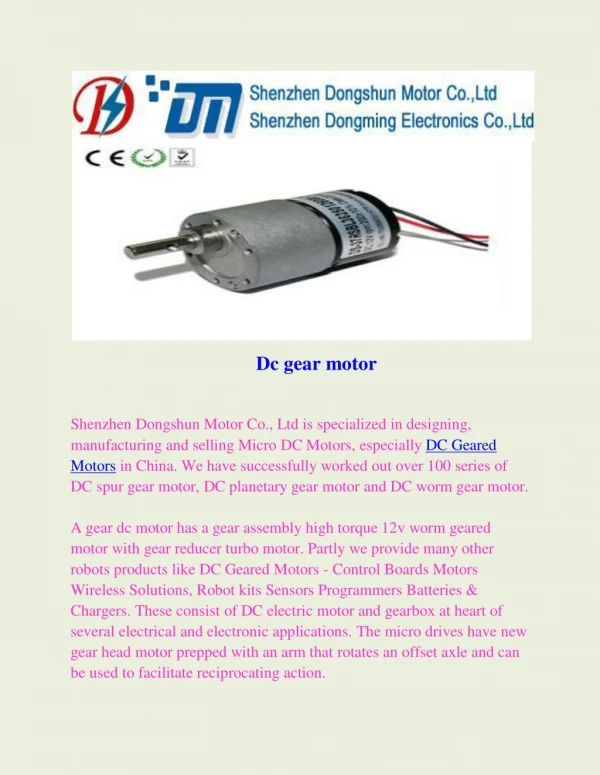
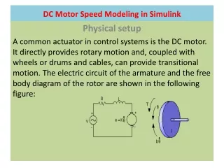
International Journal of Trend in Scientific Research and Development (IJTSRD) @ www.ijtsrd.com eISSN: 2456-6470 B. Black-box Modeling Figure3. Black Box Model In Fig. 3, a black-box model is simply the functional relationship between system input and system output without any knowledge of its internal workings. Experimental or black-box modeling also called system identification, is based on measurements. Advantages of black-box modeling are to develop easier than theoretical models and applicable over wide ranges of operating conditions. C.Gray-box Modeling In many practical cases, it often occurs that one knows only a little bit about the system, that is, the system modeling is based on the recorded input and output data with some prior knowledge about the system, e.g., the structure and order of the system. By analyzing and extracting information from the system and using the identification methods for the black-box model, a gray-box model will be constructed. IV. SYSTEM IDENTIFICATION System identification uses the input and output signals that measured from a system to estimate the values of adjustable parameters in a given model structure. The main idea of system identification is studying the behavior of existing structures by recording the output or input-output relationship of the system. The input-output description of a discrete-time system consists of a mathematical expression which explicitly defines the relationship between the input and output signals. The system is assumed to be a "black- box"to the user. So this philosophy for identifying the specifications of the system (structure) is system identification. On the other hand, each system (structure) is the same as a filter to convert the input signals with the specific frequency and characteristics to the output signals with filtered frequencies due to system parameters. So the process of constructing models from experimental data is called system identification shown in Fig. 4. And an example of input and output data arrays are presented in equation (2) and (3) respectively. Figure1. Electromechanical Characteristics of DC Motor The next important thing is to deal with the mechanical representation of the motor. Fig. 1 shows the model along with the electrical characteristics and it directly provides rotary motion and coupled with wheels or drums, and cables can provide translational motion [4, 5]. The equivalent circuit for a DC motor is represented in Fig.1 and Fig. 2 represents a 12V DC gear motor used in this research. Figure2. 12V DC Gear Motor And, the motor transfer function is calculated by equation (1). Where, T(s) = transfer function of DC motor Ke = motor back emf constant Kt = motor torque constant R = resistance of motor rotor (armature) L = inductance of armature B = motor friction coefficient J = motor of inertia III. Modeling of a System System modeling is the process of developing abstract models of a system, with each model presenting a different view or perspective of that system. There are three categories of mathematical modeling: white-box (physical) modeling, gray-box modeling and black-box (experimental) modeling [6]. A.White-box Modeling If the physical laws governing the behavior of the system are known, it is called a white-box model in which all parameters and variables can be interpreted in terms of physical entities and all parameters are known. Figure4.System Identification = [ ( ), 2 ( F ), 3 ( F ),..., ( )] meas u y F T T T F NT Equation (2) s s s s = [ ( ), 2 ( y ), 3 ( y ),..., ( )] y T T T y NT Equation (3) meas s s s s @ IJTSRD | Unique Paper ID – IJTSRD26475 | Volume – 3 | Issue – 5 | July - August 2019 Page 738
International Journal of Trend in Scientific Research and Development (IJTSRD) @ www.ijtsrd.com eISSN: 2456-6470 V. In this section, the relationship of the input and output of motor taken from the experimental hardware setup is described in section A. In sectionB, it is described about Matlab System Identification Toolbox, insertion of input dataset and estimation of models for the system. And, about the model estimation of linear, state-space and nonlinear of the system are expressed in details in section C, D and E. A.Taking Input and Output Data from Experiment Firstly, the input (pwm) and output (cycles per seconds) data of DC gear motor are taken from the experimental setup as shown in Fig. 5. And, different input types such as square wave, sine wave and sawtooth wave are applied in the real experiment and all of the output are noted. By this way, the relationship between the input and output of the system are taken. By applying these input-output data, dynamic model of the system can be observed by using the System Identification of MATLAB. Implementation of the Research The toolbox provides identification techniques such as maximum likelihood, prediction-error minimization (PEM), and subspace system identification. To represent nonlinear system dynamics, it can estimate Hammerstein-Weiner models and nonlinear ARX models with wavelet network, tree-partition, and sigmoid network nonlinearities. The toolbox performs gray-box system identification for estimating parameters of a user-defined model. It can use the identified model for system response prediction and plant modeling in Simulink. The toolbox also supports time- series data modeling and time-series forecasting [7]. As first, the System Identification Toolbox window is found by using ident tools command as shown in Fig. 6. In Fig. 7 and Fig. 8, time-domain input and output data from workspace is imported with 0.01 sampling time. In there, the square wave data set is used for finding the system model of linear, state-space and nonlinear. When being observed all types of model, other different datasets (sawtooth and sine wave) is applied to these model for validation of these models. And finally, the best model will be chosen by comparing all these models. Figure5. Hardware Experimental Setup B.MATLAB System Identification Toolbox The toolbox provides MATLAB functions, Simulink MATLAB System Identification blocks, and an application for constructing mathematical models of dynamic systems from measured input-output data. It lets create and use models of dynamic systems not easily modeled from first principles or specifications. Time-domain and frequency-domain input- output data can be used to identify continuous-time and discrete-time transfer functions, process models, state-space models, nonlinear models and so on. The toolbox also provides algorithms for embedded online parameter estimation. Figure7. Importing Input-output Data Input and output signals 300 200 y1 100 0 0 5 10 15 20 25 300 200 u1 100 0 0 5 10 15 20 25 Time Figure8. Input and Output Signals C.Identifying Linear Transfer Function Model The general transfer function model structure is: ) ( ) ( E s U s den Y(s), U(s) and E(s) represents the Laplace transforms of the output, input and error, respectively. num(s) and den(s) num s = + ( ) ( ) Y s s Equation (4) ( ) Figure6. MATLAB System Identification Toolbox Window @ IJTSRD | Unique Paper ID – IJTSRD26475 | Volume – 3 | Issue – 5 | July - August 2019 Page 739
International Journal of Trend in Scientific Research and Development (IJTSRD) @ www.ijtsrd.com eISSN: 2456-6470 represent the numerator and denominator polynomials that define the relationship between the input and the output. The roots of the denominator polynomial are referred to as the model poles. The roots of the numerator polynomial are referred to as the model zeros. The System Identification Toolbox estimates the numerator and denominator polynomials, and input/output delays from the data [7]. It must specify the number of poles and zeros to estimate a transfer function model. Here, one zero and two poles transfer function is estimated and transfer function with 71.31% fitness of simulated model with the measured model is taken and expressed in equation 7 and Fig. 9. 0536 . 0 773 . 1 2 + + s s Measured and simulated model output E.Identifying Nonlinear Model Of actually, all physical systems are nonlinear to an extent. A system in which the input-output steady-state relation is nonlinear is called nonlinear system. Because nonlinear models are able to describe the system behaviour in a much larger operating region than corresponding linear models, it is reasonable and necessary to characterize or predict the behavior of real nonlinear processes directly using nonlinear models to improve identification performance over their whole operating range. Therefore, it leads to the development ofapproaches for nonlinear modeling and analyzing nonlinear systems [7]. In System Identification Toolbox, there are two model types as nonlinear ARX and Hammerstein-Wiener. In this research, the Hammerstein-Wiener model is estimated. Hammerstein- wiener structure consists of two nonlinear blocks in series with a linear block as presented in Fig. 11 and the fitness of Hammerstein-Wiener model is 94.2% by comparing with the measured model as shown in Fig. 12. + s = TF Equation (5) . 2 461 . 0 05838 250 simulated output measured output 200 150 PWM 100 Figure11. Hammerstein-Wiener Model 50 Measured and simulated model output 250 0 0 5 10 15 20 25 simulated output measured output Time Figure9. Measured and Simulated Output for Linear Transfer Function Model 200 D.Identifying State Space Model The general state-space model structure (innovation form) is: dx + + = 150 PWM 100 50 ( ) ( ) ( ) Ax t Bu t Ke t Equation (6) dt y 0 = + + ( ) ( ) ( ) ( ) t Cx t Du t e t Equation (7) 0 5 10 15 20 25 Time Where, y(t) = the output at time t, u(t) = the input at time t, x(t) = the state vector at time t, and e(t) = the white-noise disturbance. The System Identification Toolbox estimated the state space matrices A, B, C, D, and K from the data. And, Fig. 10 illustrated the fitness of the simulated model with the measured model is 69.2%. The estimated A, B, C, D and E are in following. Figure12. Measured and Simulated Output for Hammerstein-Wiener Model Validation of Simulated Models and Results COMPARISON VI. A.Validation of Simulated Models Fig. 13 shows a Simulink model for model validation that consists of three different transfer function models. The first is for linear, the second is for state space and the last is for nonlinear Hammerstein-Wiener. These all models are taken from square wave input-output dataset using System Identification Toolbox as presented in section V. In this section, sine wave and sawtooth waves are imported as inputs to these three models. And then, the simulated model's outputs are compared with real time experiment outputs for the validation of these model whether the model taken from MATLAB System Identification Toolbox is identical or different with real time plant or system. In other words, how much the simulated model represents the actual model. Measured and simulated model output 250 simulated output measured output 200 150 PW M 100 50 0 0 5 10 15 20 25 Time Figure10. Measured and Simulated Output for State- Space Model @ IJTSRD | Unique Paper ID – IJTSRD26475 | Volume – 3 | Issue – 5 | July - August 2019 Page 740
International Journal of Trend in Scientific Research and Development (IJTSRD) @ www.ijtsrd.com eISSN: 2456-6470 TABLE I. Model Fitness Comparison Fitness of Simulated Model Linear Transfer Function Model State Space Model Nonlinear Hammerstein- Wiener Model 71.31% 69.2% 94.2% VII. The model of DC motor is estimated by using System Identification or black-box modeling without knowing any parameters of the system or its internal working. It can also estimate the nonlinear model and it has better accuracy than any other model. In this research, three models of linear, state space and nonlinear are taken out. When these model outputs are validated with actual hardware results, the simulated result of the nonlinear model is nearly identical with actual output. ACKNOWLEDGMENT The author is highly grateful to her supervisor, Dr. Nay Min Tun, Lecturer, Department of Electronic Engineering, Mandalay Technological University, for his supervision, patient guidance, support, encouragement and tolerance helped in all the time of this research work. REFERENCES [1]Modeling and Parameter Identification of a DC Motor Using Constraint Optimization Technique, Surajudeen Adewusi1, Mechanical Engineering Department, Jubail University College CONCLUSION Figure13. Validation of Simulated Models B.Comparison of Results The results comparison of above Simulink model for sawtooth and sine wave inputs are expressed in Fig. 14 and Fig. 15 respectively. For both figures, the blue is input waveform and the black line is output result from the hardware experiment. And the other lines are estimated model simulation results. By comparing hardware actual outputs with simulated results, system identification or black-box modeling can take out well the models of the unknown system. All of them, it has been found that the nonlinear model is the best accuracy model as shown in Table1. input linear state space nonlinear actual 200 [2]Nonlinear Modeling and Identification of a DC Motor for Bidirectional Operation Experiments, Tolgay Kara, IIlyas Eker, Department of Electrical and Electronics Engineering, Division of Control Systems, University of Gaziantep, 27310 Gaziantep, Turkey with Real Time 150 PWM 100 50 [3]System Identification Application Using Hammerstein Model, SABAN OZER1, HASAN ZORLU1, and SELCUK METE2D, department of Electrical and Electronic Engineering1, Erciyes University, 38039 Kayseri, Turkey, Kayseri Regional Office2, Turk Telekom A.S., 38070 Kayseri, Turkey 0 0 5 10 15 20 25 30 Cycles per seconds Figure14. Model Validation with Sawtooth Wave Input input linear state space nonlinear actual [4]Identification and Control of DC Motors, Darshan Ramasubramanian, September 2016, Automatic Control and Robotics, Superiord’Enginyeria Industrial de Barcelona Escola Tècnica 200 [5]Real Time Model Validation and Control of DC Motor Using MATLAB and USB, MOHAMMED FAROOQ MOHAMMED SALIH, Faculty of Electrical Engineering, Universiti Teknologi Malaysia, JUNE 150 PWM [6]Black-box Models from Input-Output Measurements, Lennart Ljung, Div. of Automatic control, Linkoping University, Sweden 100 50 [7]http://www.mathworks.com 0 0 5 10 15 20 Cycles per seconds Figure15. Model Validation with Sine wave Input @ IJTSRD | Unique Paper ID – IJTSRD26475 | Volume – 3 | Issue – 5 | July - August 2019 Page 741