Download
1 / 6
60 likes | 102 Views
The best way to evaluate a functioning go kart would be testing its performance under various conditions and points. Therefore, a new go kart called Mech Tech initial was presented in this report. Mech Tech initial was constructed based on the common go kart size found in the market but with slight difference in the frame design. Mech Tech initial's chassis was built using steel pipes, bent and welded together, with consideration to the position, braking system, steering system, seat position and many more. Other go kart's components such as engine, seat, steering wheel, brake system, bumper and wheels are mounted to chassis to test the performance. The chassis dimensions were taken for further testing and future reference. Among the tests applied are weight distribution on each wheel, and 17 degree method. Srinivasa Reddy | N. Sharathchandra | Mustafa | P. Jayanth "Modelling and Analysis of Go-Kart Chassis" Published in International Journal of Trend in Scientific Research and Development (ijtsrd), ISSN: 2456-6470, Volume-3 | Issue-3 , April 2019, URL: https://www.ijtsrd.com/papers/ijtsrd23268.pdf Paper URL: https://www.ijtsrd.com/engineering/mechanical-engineering/23268/modelling-and-analysis-of-go-kart-chassis/srinivasa-reddy<br>

E N D
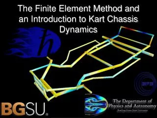
International Journal of Trend in Scientific Research and Development (IJTSRD) Volume: 3 | Issue: 3 | Mar-Apr 2019 Available Online: www.ijtsrd.com e-ISSN: 2456 - 6470 Modelling and Analysis of Go-Kart Chassis Srinivasa Reddy1, N. Sharathchandra2, Mustafa2, P. Jayanth2 1Assistant Professor, 2Student 1,2Department of Mechanical Engineering, Guru Nanak Institute of Technology, Rangareddy, Telangana, India How to cite this paper: Srinivasa Reddy | N. Sharathchandra | Mustafa | P. Jayanth "Modelling and Analysis of Go- Kart Chassis" Published in International Journal of Trend in Scientific Research and Development (ijtsrd), ISSN: 2456- 6470, Volume-3 | Issue-3, April 2019, pp.1233-1238, URL: https://www.ijtsrd.c om/papers/ijtsrd23 268.pdf Copyright © 2019 by author(s) and International Journal of Trend in Scientific Research and Development Journal. This is an Open Access article distributed under the terms of the Creative Commons Attribution License (CC BY 4.0) (http://creativecommons.org/licenses/ by/4.0) INTRODUCTION Usually a go-kart driver or owner who wants to improve the handling of the vehicle will purchase the latest in wheels, tyres and other optional equipment, but end up finding that those things in fact handles worse. The first stage in achieving a good handling kart that will provide the greatest percentage of efficiency is to go right back to basics. The chassis is the framework of any vehicle. The suspension, steering, and drivetrain components (such as engine, transmission and final drive components) are mounted to chassis. The chassis is the framework of any vehicle. The chassis would have to be strong and rigid platform to support the suspension components (James D.Halderman, Chase D.Mitchell, Jr.Automotive Chassis Systems, 2000, p.1). Furthermore, the constructions of today's vehicles require the use of many different materials. Chassis of a go-kart is not much different from a normal car chassis, in fact, it is much less complicated. The different in size and weight make go-kart chassis much easier to design and construct. DESIGN OF GO-KART CHASSIS A typical dictionary definition of chassis usually includes terms such as framework on which the body or working parts of a vehicle, radio or television are built(Oxford Advanced Learner's Dictionary,p.190).There are three basic designs used today frame, unit-body and space frame construction. ABSTRACT The best way to evaluate a functioning go-kart would be testing its performance under various conditions and points. Therefore, a new go-kart called Mech Tech- initial was presented in this report. Mech Tech initial was constructed based on the common go-kart size found in the market but with slight difference in the frame design. Mech Tech-initial’s chassis was built using steel pipes, bent and welded together, with consideration to the position, braking system, steering system, seat position and many more. Other go-kart’s components such as engine, seat, steering wheel, brake system, bumper and wheels are mounted to chassis to test the performance. The chassis dimensions were taken for further testing and future reference. Among the tests applied are weight distribution on each wheel, and 17-degree method. The chassis of go-kart is a skeleton frame made up of pipes and other materials of various cross-sections. The chassis of go-kart must consist of stability, torsionol, rigidity, as well as it should have relatively high degree of flexibility as there is no suspension. It can also have adequate strength to sustain load of operator and other accessories. The chassis is designed by ensuring convenience and safety of operator. The chassis was designed for a safe ride and the load is applied on it without compromising the structural strength. DIMENSIONS OF GO-KART CHASSIS IJTSRD23268 Figure Dimensions of Go-Kart Chassis @ IJTSRD | Unique Paper ID – IJTSRD23268 | Volume – 3 | Issue – 3 | Mar-Apr 2019 Page: 1233
International Journal of Trend in Scientific Research and Development (IJTSRD) @ www.ijtsrd.com eISSN: 2456-6470 MATERIALS USED IN GO-KART CHASSIS Most of the automotive components and parts are made of cast iron, such as brake drums and rotors, spindles, engine blocks, and many other components including fasteners. There are different types of steel for each component, which requires different strengths and characteristic from the material. The amount of carbon in steel is the most important point in determining the strength, hardness, and machining characteristics. (CEE) and the McAfee Professor of Engineering; Zhao Qin, a CEE research scientist; Gang Seob Jung, a graduate student; and Min Jeong Kang MEng ’16, a recent graduate. A team of MIT engineers has successfully designed a new 3-D material with five percent the density of steel and ten times the strength, making it one of the strongest lightweight materials known. Video: Melanie Gonick/MIT Galvanized steel Galvanized steel is steel with zinc coating which could protect the steel from corrosion(rust).Another type of rust- resistance steel includes zincometal, which is a two-coat bake-on system using chromium oxide and zinc. Other groups had suggested the possibility of such lightweight structures, but lab experiments so far had failed to match predictions, with some results exhibiting several orders of magnitude less strength than expected. The MIT team decided to solve the mystery by analysing the material’s behaviour down to the level of individual atoms within the structure. They were able to produce a mathematical framework that very closely matches experimental observations. High-Strength Steel High-strength steel (HSS) has been introduced widely since the mid-1970s, as many car and light truck parts have built with it. Application of HSS is commonly in sill area under the doors where high strength is required, yet lightweight is needed. Other applications in vehicles are in the bumper supports and impact beams in doors. Two-dimensional materials — basically flat sheets that are just one atom in thickness but can be indefinitely large in the other dimensions — have exceptional strength as well as unique electrical properties. But because of their extraordinary thinness, “they are not very useful for making 3-D materials that could be used in vehicles, buildings, or devices,” Buehler says. “What we’ve done is to realize the wish of translating these 2-D materials into three- dimensional structures.” HSS is very hard, but heating causes it to lose much of its strength. High-strength steel is low-carbon alloy steel which consists of various amounts of carbon, silicon, phosphorus, nitrogen, and manganese (Kalpak Jian, Manufacturing Engineering and Technology, 1995, p.166). Body repair technicians should always recommended procedures to avoid weakening the structure of the body. follow manufacturers' The team was able to compress small flakes of graphene using a combination of heat and pressure. This process produced a strong, stable structure whose form resembles that of some corals and microscopic creatures called diatoms. This shapes, which have an enormous surface area in proportion to their volume, proved to be remarkably strong. “Once we created these 3-D structures, we wanted to see what’s the limit — what’s the strongest possible material we can produce,” says Qin. To do that, they created a variety of 3-D models and then subjected them to various tests. In computational simulations, which mimic the loading conditions in the tensile and compression tests performed in a tensile loading machine, “one of our samples has 5 percent the density of steel, but 10 times the strength,” Qin says. Gray Cast iron Gray cast iron is one of the oldest ferrous metals used in construction and composed of iron(Fe), carbon(c) and silicon(Si) but also contain traces of sulphur(s), manganese(Mn) and phosphorus(p).It contains high carbon content of 2% to 5%. It is hard, brittle, non-malleable, and more fusible than steel. Structural steel It is a category of steel used as a construction material for making structural steel shapes. It is a profile formed with a specific cross section and following certain standards. It has properties such as strength, toughness, ductility, weldability, and durability. Buehler says that what happens to their 3-D graphene material, which is composed of curved surfaces under deformation, resembles what would happen with sheets of paper. Paper has little strength along its length and width, and can be easily crumpled up. But when made into certain shapes, for example rolled into a tube, suddenly the strength along the length of the tube is much greater and can support substantial weight. Similarly, the geometric arrangement of the graphene flakes after treatment naturally forms a very strong configuration. LATEST RESEARCH ON MATERIALS A team of researchers at MIT has designed one of the strongest lightweight materials known, by compressing and fusing flakes of grapheme, a two-dimensional form of carbon. The new material, a sponge-like configuration with a density of just 5 percent, can have a strength 10 times that of steel.In its two-dimensional form, graphene is thought to be the strongest of all known materials. But researchers until now have had a hard time translating that two-dimensional strength into useful three-dimensional materials. The new configurations have been made in the lab using a high-resolution, multilateral 3-D printer. They were mechanically tested for their tensile and compressive properties, and their mechanical response under loading was simulated using the team’s theoretical models. The results from the experiments and simulations matched accurately. The new findings show that the crucial aspect of the new 3-D forms has more to do with their unusual geometrical configuration than with the material itself, which suggests that similar strong, lightweight materials could be made from a variety of materials by creating similar geometric features.The findings are being reported today in the journal Science Advances, in a paper by Markus Buehler, the head of MIT’s Department of Civil and Environmental Engineering The new, more accurate results, based on atomistic computational modelling by the MIT team, ruled out a @ IJTSRD | Unique Paper ID – IJTSRD23268 | Volume – 3 | Issue – 3 | Mar-Apr 2019 Page: 1234
International Journal of Trend in Scientific Research and Development (IJTSRD) @ www.ijtsrd.com eISSN: 2456-6470 possibility proposed previously by other teams: that it might be possible to make 3-D graphene structures so lightweight that they would actually be lighter than air, and could be used as a durable replacement for helium in balloons. The current work shows, however, that at such low densities, the material would not have sufficient strength and would collapse from the surrounding air pressure. This work, Gao says, “shows a promising direction of bringing the strength of 2-D materials and the power of material architecture design together.” The research was supported by the Office of Naval Research, the Department of Defence Multidisciplinary University Research Initiative, and BASF-North American Centre for Research on Advanced Materials. But many other possible applications of the material could eventually be feasible, the researchers say, for uses that require a combination of extreme strength and light weight. MODELLNG OF GO-KART CHASSIS IN CATIA Tools used in modeling of go-kart chassis Sketch Line Constrain toolbar Sweep Split Joint Trim Overview of go-kart chassis Dimensions to be considered in modeling of go-kart chassis “You could either use the real graphene material or use the geometry we discovered with other materials, like polymers or metals,” Buehler says, to gain similar advantages of strength combined with advantages in cost, processing methods, or other material properties (such as transparency or electrical conductivity). “You can replace the material itself with anything,” Buehler says. “The geometry is the dominant factor. It’s something that has the potential to transfer to many things.” The unusual geometric shapes that graphene naturally forms under heat and pressure look something like a Nerf ball — round, but full of holes. These shapes, known as gyroids, are so complex that “actually making them using conventional manufacturing methods is probably impossible,” Buehler says. The team used 3-D-printed models of the structure, enlarged to thousands of times their natural size, for testing purposes. For actual synthesis, the researchers say, one possibility is to use the polymer or metal particles as templates, coat them with graphene by chemical vapour deposit before heat and pressure treatments, and then chemically or physically remove the polymer or metal phases to leave 3-D graphene in the gyroid form. For this, the computational model given in the current study provides a guideline to evaluate the mechanical quality of the synthesis output. Figure Constraints of Go-Kart Chassis Model ISOMETRIC VIEW OF GO-KART CHASSIS The same geometry could even be applied to large-scale structural materials, they suggest. For example, concrete for a structure such as a bridge might be made with this porous geometry, providing comparable strength with a fraction of the weight. This approach would have the additional benefit of providing good insulation because of the large amount of enclosed airspace within it. Because the shape is riddled with very tiny pore spaces, the material might also find application in some filtration systems, for either water or chemical processing. The mathematical descriptions derived by this group could facilitate the development of a variety of applications, the researchers say. Figure Isometric Viwe of Go-Kart Chassis SIDE VIEW OF GO-KART CHASSIS “This is an inspiring study on the mechanics of 3-D graphene assembly,” says Huajian Gao, a professor of engineering at Brown University, who was not involved in this work. “The combination of computational modelling with 3-D- printing-based experiments used in this paper is a powerful new approach in engineering research. It is impressive to see the scaling laws initially derived from Nano scale simulations resurface in macro scale experiments under the help of 3-D printing,” he says. Figure Side View of Go-Kart Chassis @ IJTSRD | Unique Paper ID – IJTSRD23268 | Volume – 3 | Issue – 3 | Mar-Apr 2019 Page: 1235
International Journal of Trend in Scientific Research and Development (IJTSRD) @ www.ijtsrd.com eISSN: 2456-6470 FRONT VIEW OF GO-KART CHASSIS ANALYSIS The data set prepared by the pre-processor is used as an input to the finite element code itself, which constructs and solves a system of linear or non-linear algebraic equations. Where, u and f are displacements and extremely applied forces at the nodal points. One of FEA’s principle advantages is that many problem types can be addressed with the same code, merely by specifying the appropriate type from the library. POSTPROCESSING In the earlier days of finite elements analysis, the user would pore through reuse of numbers generated by the pore, Listing displacem1ents and stresses at discrete positions within the model. It is easy to miss important trends and hot spots this way, and modern codes used graphical displays to assist in visualization the results. A typical post processor display overlays colored contours representing stress level on the model, showing a fulfilled picture similar to that of photo elastic or moiré experimental results. RESULTS AND DISCUSSIONS After giving supports and loads click on the Solve. It takes 2 to 3 minutes to calculate the results Figure Front View of Go-Kart Chassis TYPE OF ENGINEERING ANALYSIS STUCTURAL Analysis consists of linear and non-linear models. Linear models use simple parameters and assume that material is not plastically deformed. Non- linear models consist of stressing the materials past its elastic capacities. The stresses in material then vary with amount of deformation as in. VIBRATIONAL Analysis is used to test a material against random vibrations, shock and impact. Each of these incidents may act on the natural vibrational frequency of material which in turn may cause resonance and subsequent failure. FATIGUE Analysis helps designers to predict the life of the materials or structure by showing the effects of cyclic loading on the specimen. Such analysis can show the areas where crack propagation is most likely occur. Failure due to fatigue may also show the damage tolerance of the material. HEAT TRANSFER Analysis models the conductivity or thermal fluid dynamics of the material or structure. This may consist of steady state or transient transfer. Steady state transfer refers to constants thermal properties in the material that yield linear heat diffusion. Figure Solution Status Deformation, stresses and strains are to be added to the solution which is after the static structural. These are given by right click on the solution then select insert command. After completion of the solution take the images of the results. These are shown in below figures. Results Appearing for Structural Steel Material Are As Follows Total Deformation Equivalent Stress Maximum Principle Stress Minimum Principle Stress Maximum Shear Stress RESULTS OF FINITE ELEMENT ANALYSIS FEA has become a solution of task of predicting failure due to unknown stresses by showing problem areas in a material and allowing designers to see all the theoretical stresses within. This method of product design and testing is far superior to manufacturing cost which would accrue if each sample was actually built and tested. In practice, a finite element analysis usually consists of three principal stresses. PREPROCESSING The user constructs a model of a part to be analyzed in which the geometry is divided into number of discrete sub region of element,” Connected at discrete point called nodes”. Certain of these nodes will have fixed displacements, and other will have prescribed loads. These models can be extremely time consuming to prepare, a commercial code via with one another to have the most user friendly graphical “pre-processor” to assist in this rather tedious chore. Some of these pre-processors can over lay a mess on a pre- existing CAD file, So, that finite element analysis can be done conveniently as part of the computerized drafting-and- design process. Figure Total Deformation @ IJTSRD | Unique Paper ID – IJTSRD23268 | Volume – 3 | Issue – 3 | Mar-Apr 2019 Page: 1236
International Journal of Trend in Scientific Research and Development (IJTSRD) @ www.ijtsrd.com eISSN: 2456-6470 Figure Maximum Principle Stress Figure Equivalent Stress Figure Minimum Principle Stress Figure Maximum principle Stress Results Appearing for Gray Cast Iron Material Are As Follows, Total Deformation Equivalent Stress Maximum Principle Stress Minimum Principle Stress Maximum Shear Stress Figure Maximum Shear stress Comparison of results Test Structural Steel Deformation Equivalent Stress Maximum Stress Minimum Stress Shear Stress CONCLUSION In this project, we had modeled and did analysis for the go- kart chassis. The 3D model of Go-kart chassis was done in CATIA V5 CAD software and analysis of the same was done in ANSYS 16.0 CAE software. The static structural analysis of GO-KART CHASSIS was done with two different materials i.e. structural steel and gray cast iron. The analysis was done with two materials and the values of total deformation, equivalent stress, maximum principal stress, minimum principal stress and shear stress was found for the load of 600N. It was found that it is less than yield strength values which are 250 for steel and 200 for gray cast iron which means it’s safe for the passengers in the car. Gray Cast Iron 0.00014513 m 7.1027e6 pa 7.1262e6 pa 1.8634e6 pa 3.5797e6 pa 0.00014371 m 6.8654e6 pa 6.8274e6 pa 1.85e6 pa 3.6e6 pa Figure Total deformation Figure Equivalent Stress @ IJTSRD | Unique Paper ID – IJTSRD23268 | Volume – 3 | Issue – 3 | Mar-Apr 2019 Page: 1237
International Journal of Trend in Scientific Research and Development (IJTSRD) @ www.ijtsrd.com eISSN: 2456-6470 So, we conclude as per our analysis using structural steel and gray cast iron is best and also our design is safe. REFERENCES [1]Abhinay Nilawar, Harmeet Singh Nannade, Amey Pohankar, Nikhil Selokar, “DESIGN OF GO-KART”, Maharashtra,India, IJFEAT, ISSN: 2321-8134. IJETMAS, Volume 4, ISSUE 2, ISSN 2349-4476, February 2016. [4]Ammar Qamar Ul Hasan, “SIMULATION OF ATV ROLL CAGE TESTING”, IOSR-JMCE, e-ISSN: 2278-1684, P- ISSN: 2320-334x, Volume 12, Issue 3 Ver. Ii, Pp 45-49, May. - Jun. 2015. [5]N. R. Patil, Ravichandra R. Kulkarni, Bhushan R. Mane, Suhil H. Malve, “STATIC ANALYSIS OF GO-KART CHASSIS FRAME BY ANALYTICAL AND SOLIDWORKS SIMULATION”, IJSET, ISSN : 2277-1581,Volume No.3, Issue No.5, pp : 661-663, 1 May 2014. [2]Shubham Kolhe , Vrushabh U. Joijode, “ROLL CAGE DESIGN AND ANALYSIS FOR FORMULA STUDENT RACE CAR”, IJESRT, ISSN: 2277-9655, July 2016. [3] Koustubh Hajare, Yuvraj Shet, Ankush Khot, “A Review Paper On Design And Analysis Of A Go-Kart Chassis”, @ IJTSRD | Unique Paper ID – IJTSRD23268 | Volume – 3 | Issue – 3 | Mar-Apr 2019 Page: 1238


![[PDF] DOWNLOAD EBOOK Go Kart Racing Log: Go Kart Journal for Training Circu](https://cdn7.slideserve.com/12465184/go-kart-racing-log-go-kart-journal-for-training-dt.jpg)