Download
1 / 4
40 likes | 54 Views
There are various types of microstrip antenna that can be used for many applications in communication systems. This paper presents the design of a folded shorted patch antenna FSPA for the application of Radio Frequency RF energy harvesting system capable of receiving radio frequency of GSM 900 band 860MHz to 960MHz . The antenna is designed using microstrip technology on an FR 4 substrate with a dielectric constant of 4.4 and a thickness of 1.6. The antenna was designed and simulated using FEKO, the Electromagnetic solver software. One slot is incorporated into the upper patch of the FSPA. Simulated results show that this antenna can attain an impedance bandwidth of 32MHz from 884MHz to 916MHz at the center frequency of 900MHz with the slot. The results also reveal the good unidirectional radiation pattern and the stable gain over the operating frequency. This antenna is well compatible with using RF energy harvesting to receive the signal of the GSM 900 band. Aye Thet Mon | Chaw Myat Nwe "Folded Shorted Patch Antenna with Slots for RF Energy Harvesting in Wireless Sensor Network" Published in International Journal of Trend in Scientific Research and Development (ijtsrd), ISSN: 2456-6470, Volume-3 | Issue-5 , August 2019, URL: https://www.ijtsrd.com/papers/ijtsrd26476.pdf Paper URL: https://www.ijtsrd.com/engineering/electronics-and-communication-engineering/26476/folded-shorted-patch-antenna-with-slots-for-rf-energy-harvesting-in-wireless-sensor-network/aye-thet-mon<br>

E N D
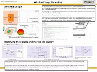
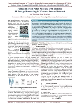
International Journal of Trend in Scientific Research and Development (IJTSRD) Volume 3 Issue 5, August 2019 Available Online: www.ijtsrd.com e-ISSN: 2456 – 6470 Folded Shorted Patch Antenna with Slots for RF Energy Harvesting in Wireless Sensor Network Aye Thet Mon, Chaw Myat Nwe Department of Electronic Engineering, Mandalay Technological University, Mandalay, Myanmar How to cite this paper: Aye Thet Mon | Chaw Myat Nwe "Folded Shorted Patch Antenna with Slots for RF Energy Harvesting in Wireless Sensor Network" Published in International Journal of Trend in Scientific Research and Development (ijtsrd), ISSN: 2456- 6470, Volume-3 | Issue-5, August 2019, https://doi.org/10.31142/ijtsrd26476 Copyright © 2019 by author(s) and International Journal of Trend in Scientific Research and Development Journal. This is an Open Access article distributed under the terms of the Creative Commons Attribution License (CC (http://creativecommons.org/licenses/by /4.0) RF energy harvesting systems have been developed and widely used in the mobile radio, Wi-Fi systems, radio, television broadcasting system, wireless LANs (WLANs), GSM-900, GSM-1800, LTE, Wi-Fi, and WiMax and rectified into a usable DC voltage. Energy harvesting is a process by which energy obtained from the environment can be converted into usable power that is used for any kind of low power devices. ABSTRACT There are various types of microstrip antenna that can be used for many applications in communication systems. This paper presents the design of a folded shorted patch antenna (FSPA) for the application of Radio Frequency (RF) energy harvesting system capable of receiving radio frequency of GSM- 900 band (860MHz to 960MHz). The antenna is designed using microstrip technology on an FR-4 substrate with a dielectric constant of 4.4 and a thickness of 1.6. The antenna was designed and simulated using FEKO, the Electromagnetic solver software. One slot is incorporated into the upper patch of the FSPA. Simulated results show that this antenna can attain an impedance bandwidth of 32MHz from 884MHz to 916MHz at the center frequency of 900MHz with the slot. The results also reveal the good unidirectional radiation pattern and the stable gain over the operating frequency. This antenna is well compatible with using RF energy harvesting to receive the signal of the GSM- 900 band. KEYWORDS: Folded Shorted Patch Antenna (FSPA), Microstrip, RF Energy Harvesting, and GSM-900 band I. INTRODUCTION There are so many energy harvesting sources such as Radio Frequency (RF) energy sources, wind energy, water energy, acoustic noise, thermo-electric, vibration, piezoelectric, mobile phone base station, etc., having different power densities from where we can get electric power if it is harvested very effectively. It is where different types of electromagnetic waves are used to transmit and receive information from long distances. upper-frequency band and high gain. A compact and wideband antenna is desirable for all modern wireless communication systems. FSPA antenna is used to reduce the physical size of the patch. [2] Therefore, it is capable to cover the operating bandwidth of several wireless communication systems. This antenna can be used as a receiving antenna for capturing the signal of GSM 900 band. In this paper, new HUE-slotted FSPA is presented that covers the frequency ranges from 884MHz to 916MHz that is equivalent to 32MHz impedance bandwidth. These results indicate that this antenna can be performed as harvesting antenna for receiving the signal of GSM 900 band at the range of 860 MHz to 960MHz. It is also observed from the results of radiation pattern and gain that radiation pattern is unidirectional and good over the operating ranges of frequencies and the value of gain is not stable in the same range of frequencies. II. Antenna Parameters The design of receiving antenna is vital since the parameters of the antenna such as return loss, impedance bandwidth, radiation pattern and gain can affect the volume of harvestable energy. [3] A.Return Loss Return loss is the difference between transmitted and reflected power in a system. For a well-designed antenna, the return loss should be at least -10dB. IJTSRD26476 pp.742-745, BY 4.0) RF energy harvesting system consists of three parts. An efficient antenna for maximizing the reception of the RF signals. The matching network uses to achieve the maximum power delivery from the antenna to the rectifier. Optimization of the rectifier circuit for RF to DC conversion.[1] Figure1.Block Diagram of RF Energy Harvesting System The receiving antenna is an essential element for having harvesting of RF energy as it is used for absorbing energy from any nearby sources which are radiating energy. Folded Shorted Patch Antenna (FSPA) is proposed and designed for the application of Radio Frequency (RF) energy harvesting. FSPA has wide impedance bandwidth in the lower and RL= -20log dB @ IJTSRD | Unique Paper ID – IJTSRD26476 | Volume – 3 | Issue – 5 | July - August 2019 Page 742
International Journal of Trend in Scientific Research and Development (IJTSRD) @ www.ijtsrd.com eISSN: 2456-6470 B.Voltage Standing Wave Ratio (VSWR) Voltage Standing Wave Ratio (VSWR) is the ratio of the maximum voltage to the minimum voltage transmission line. It is the function of the reflection coefficient which describes the power reflected from the antenna. It is always a real and positive number for antennas. The smaller the VSWR, the better the antenna is matched to the transmission line and more power is delivered to the antenna. The minimum VSWR is 1.0. VSWR = = shorted patch antenna proposed here. HUE-slot has a great impact on the performance of the designed antenna. There are many analysis methods for the design of antenna which are discussed in previous. The following equations are the basic formulas for the design of the antenna.[4] Step 1: Calculation of the width of the patch (W) The width of the Microstrip patch antenna is given as: on the W 1(no mismatch loss) III. Antenna Geometry The top view and side view geometry of the FSPA designed in FEKO are shown in Figure 2. VSWR 2(more mismatch loss) 100.32mm where c resonant frequency relative dielectric constant Step 2: Calculate the Length (L) Effective dielectric constant ( (1) velocity of light ) (2) where h W the width of the patch Effective length ( The effective length is: which is found to be = 0.07986 (3) 4.26 the relative dielectric constant thickness of the substrate (a) ) where c velocity of light resonant frequency effective dielectric constant Length extension ( ) (4) 0.7447m (b) where h W Calculation of actual length of the patch (L) L 2 L = 78.37mm (5) where, extension effective length Step 3: Calculate the length and width of the ground plane = 87.97mm = 109.92mm The antenna is designed using microstrip, RF technology on an FR-4 substrate with a dielectric constant of 4.4 and thickness of 1.6 and the center frequency of 900MHz. The optimized dimension of the proposed antenna is given in Table I. [6] Figure 2.Complete Geometry of the Proposed Antenna (a) Top View of the Proposed HUE-Slot FSPA with Labeling (b) Side View of the Proposed FSPA with Labeling There are two rectangular-shaped patches are positioned on the top of the ground plane. Among the two patches, the patch near to the ground plane is called lower patch and the other remaining patch is called upper patch. The media between the ground plane & lower patch and also the lower and upper patch are air. The material used for making the ground plane and the patch is copper. The thickness of the ground plane and both patches is 1.6 mm. The one end of the lower patch is shorted with the ground and the other end of the patch is folded back for connecting with the upper patch in the middle of a square ground plane. The feeding technique used for exiting this proposed antenna is a coaxial feed technique. There is also one shorting post has been used between the ground plane and the lower patch. The shorting post and the coaxial feed cable are placed in the middle position of the patch along the x-axis.[5]One slot having HUE-shape is added into the upper patch of the folded thickness of the substrate the width of the patch effective dielectric constant length (6) (7) @ IJTSRD | Unique Paper ID – IJTSRD26476 | Volume – 3 | Issue – 5 | July - August 2019 Page 743
International Journal of Trend in Scientific Research and Development (IJTSRD) @ www.ijtsrd.com eISSN: 2456-6470 Table I Parameters for FSPA Parameters L Length of the lower patch h Height of each patch W Width of both patch d Diameter of feed edge Length of edge feed Length of the feed to the center post Length of the post side Length of side L1 Length of the upper patch Length of the parallel arm of the H slot, U slot, and E slot Length of the other arm of the H slot, U slot, and E slot Width of the slot T The thickness of patch and ground plane Description Value(mm) 95.0 7.00 95 1.30 30 24.5 47.5 30.0 62.0 16.0 Figure4. Simulated Return Loss over Frequency for FSPA The standard value of the voltage standing wave ratio (VSWR) for any antenna to receive the signal properly should be below 2 over the operating ranges of frequency. The voltage VSWR is below 2 for this antenna over the frequency ranges from 884MHz to 916MHz.Other important performance parameters are gain and radiation pattern. The radiation pattern and gain of this antenna at the frequency of 884MHz and 916MHz has been simulated that are shown in Figure 5, 6 and 7 correspondingly. 8 3.00 1.6 IV. By using above the antenna parameters, the FSPA antenna is designed by CADFEKO and the result is shown in POSTFEKO. In FEKO, the result of the return loss, directivity and radiation pattern are shown in Figure 4, 5, 6 and 7. Results & Discussion Figure5. Simulated Directivity of the Antenna The result of the gain shown in figure 5 is 1.42dBi at the frequency of 900MHz. (a) (b) Figure 3.Top and Side View of the FSPA Geometry Designed by FEKO (a) Top View of the Proposed HUE-Slot FSPA Designed by FEKO (b) Side View of the Proposed HUE-Slot FSPA Designed by FEKO The return loss of the antenna for the optimized dimensions as given in Table I is shown in Figure 4. The figure shows the maximum return loss is -22dB at the frequency of 900MHz it is observed that the proposed FSPA covers the frequency range from 884MHz to 916 MHz for the return loss below -10dB.Single-band obtained at 900MHz, which is in the range of GSM-900 band. So the impedance bandwidth of this antenna is 32 MHz that is equivalent to 4% at the center frequency of 900 MHz.The result describes that this antenna is well suited for receiving the signal for RF energy harvesting and then this antenna cascaded with RF energy harvesting circuit for RF energy harvesting application. [5] Figure6. 3D Radiation Pattern 0f 900MHz (a) (b) Figure7. Theta Gain (Frequency= 900 MHz) @ IJTSRD | Unique Paper ID – IJTSRD26476 | Volume – 3 | Issue – 5 | July - August 2019 Page 744
International Journal of Trend in Scientific Research and Development (IJTSRD) @ www.ijtsrd.com eISSN: 2456-6470 (a) Phi=0 (b) Phi= 90 From the above result shown in Figure 5 and Figure 6 radiation patterns for the frequency of 900 MHz are -----------directional and the -3dB beamwidth of theta gain is 95 degree at phi o degree and 92 degrees at phi 90 degrees respectively. The value of sidelobe levels at both frequencies is good since its value is below -15dB. This antenna leads to use as a part of the full RF energy harvester circuit for receiving from 860MHz to 960MHz. V. Conclusions This antenna represents a folded shorted patch antenna that can be used as an RF energy harvesting antenna for receiving the signals of GSM-band (860MHz to 960MHz). This antenna represents a compact HUE-slot patch antenna that can be used as an RF energy harvesting antenna for receiving the signals of GSM-band between884MHz to 916MHz the center frequency of900MHz.The compact size device is highly acceptable since communication technology is growing day by day.[5]Therefore this antenna proposed in this paper is mostly compact with comparing to the other folded shorted patch antenna designed before. This antenna can be connected with the RF energy harvester circuit for harvesting RF energy at the frequency ranges from 860MHz to 960MHz in the future application. ACKNOWLEDGMENT The author thanks Dr. Chaw Myat Nwe, Professor, Department of Electronics and Communication Engineering for kind permission to prepare for this paper, for his close supervision, helpful advice, encouragement and numerous invaluable guidance. The author would also thank all teachers and friends who willingly helped the author throughout the preparation of the paper. REFERENCES [1]A. Bakkali, J. Pelegri-Sebastia, “A Dual-Band Antenna for RF Energy Harvesting Systems in Wireless Sensor Networks” Journal of Sensors Volume 2016, Article ID 5725836, 8 pages [2]K. Gosalia and G. Lazzi, "Reduced size, dual-polarized microstrip patch communications," IEEE Transactions on Antennas and Propagation, vol. 51, pp. 2182-2186, 2003. antenna for wireless [3]R. Li, G. DeJean, M. M. Tentzeris, and J. Laskar, "Development and analysis of a folded shorted-patch antenna with reduced size," IEEE Transactions on Antennas and Propagation, vol. 52, pp. 555-562, 2004 [4]E. M. Ali, N. Z. Yahaya, "Design of Micro strip Patch Antenna at 900MHz for Charging Mobile Application," Journal of Engineering and Applied Science,12(4):988- 993,2017 [5]Z. W. Sim, R. Shuttle worth, M. J. Alexander, and B. D. Grieve, “Compact patch antenna design for outdoor RF energy harvesting in wireless sensor networks,” Progress In Electromagnetics Research, vol. 105, pp. 273-294, 2010. @ IJTSRD | Unique Paper ID – IJTSRD26476 | Volume – 3 | Issue – 5 | July - August 2019 Page 745