Download

1 / 4
40 likes | 65 Views
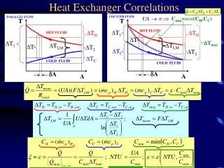
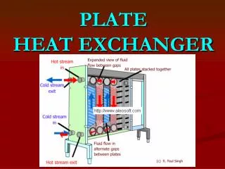
The I.C. Engines are losing large amount of heat into environment directly. This waste heat can be reused for other purpose like TEG, Air conditioning etc. A heat exchanger is a device that is used to transfer thermal energy between two or more fluids, between a solid surface and a fluid, or between solid particulates and a fluid, at different temperatures and in thermal contact. In case of TEG there is need to have temperature uniformity on surface of heat exchanger is important. So, it is important design achieve thermal uniformity for converting the heat into other form of energy effectively. Mr. Jadhav Vishal | Mr. D. S. Patil "Experimental Analysis of Automotive Exhaust Heat Exchanger for Thermal Uniformity" Published in International Journal of Trend in Scientific Research and Development (ijtsrd), ISSN: 2456-6470, Volume-2 | Issue-3 , April 2018, URL: https://www.ijtsrd.com/papers/ijtsrd11702.pdf Paper URL: http://www.ijtsrd.com/engineering/mechanical-engineering/11702/experimental-analysis-of--automotive-exhaust-heat-exchanger-for-thermal-uniformity/mr-jadhav-vishal<br>

E N D
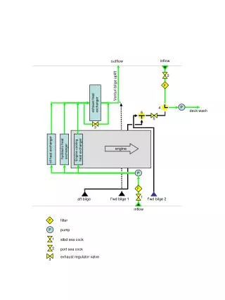
International Research Research and Development (IJTSRD) International Open Access Journal Experimental Analysis of Automotive Exhaust Heat Exchanger for Thermal Uniformity International Journal of Trend in Scientific Scientific (IJTSRD) International Open Access Journal ISSN No: 2456 ISSN No: 2456 - 6470 | www.ijtsrd.com | Volume 6470 | www.ijtsrd.com | Volume - 2 | Issue – 3 Experimental Analysis of Au tomotive Exhaust Heat Exchanger for Thermal Uniformity Mr. Jadhav Vishal Mr. D. S. Patil Mr. D. S. Patil Department of Mechanical Engineering, G. H. Raisoni College of Engineering and , Maharashtra, India Student, Department of Mechanical Engineering, G. H. Raisoni College of Engineering and Management, Pune, Maharashtra, ABSTRACT Student, Department of Mechanical Engineering, G. H. Raisoni College of Engineering and Maharashtra, India Lecturer, Department of Mechanical Engineering, G. H. Raisoni College of Engineering and Management, Pune, Maharashtra, India The I.C. Engines are losing large amount of heat into environment directly. This waste heat can be reused for other purpose like TEG, Air conditioning etc. A heat exchanger is a device that is used to transfer thermal energy between two or more fluids, between a solid surface and a fluid, or between solid particulates and a fluid, at different temperatures and in thermal contact. In case of TEG there is need to have temperature uniformity on surface of heat exchanger is important. So, it is important design achieve thermal uniformity for converting the heat into other form of energy effectively. The I.C. Engines are losing large amount of heat into environment directly. This waste heat can be reused for other purpose like TEG, Air conditioning etc. A heat exchanger is a device that is used to transfer more time for gas to remain in the cavity without affects on the back pressure of the engine. affects on the back pressure of the engine. time for gas to remain in the cavity without 2. Installation of position of heat exchanger: 2. Installation of position of heat exchanger: fluids, between a 2.1. Positioning of heat exchanger: 2.1. Positioning of heat exchanger: solid surface and a fluid, or between solid particulates and a fluid, at different temperatures and in thermal contact. In case of TEG there is need to have temperature uniformity on surface of heat exchanger The heat exchanger position is important for the more The heat exchanger position is important for the more uniform heat distribution over the surface of the heat exchanger, also the working of the exhaust system should not get affected by the position of the heat exchanger. Back pressure should not increase by this work is very significant in this installation of the heat exchanger. The installation position of TEG and propose three different cases. er the surface of the heat exchanger, also the working of the exhaust system should not get affected by the position of the heat exchanger. Back pressure should not increase by this work is very significant in this installation of the heat nstallation position of TEG and tant design achieve thermal uniformity for converting the heat into other Keywords: Exchangers, exhaust, uniformity, temperature uniformity, TEG, Case 1: Thermoelectric generator is situated at the last of exhaust system i.e. after muffler. Case2: Thermoelectric generator situated in the middle of the catalytic convertor and the muffle Case3: Thermoelectric generator is situated at the beginning i.e. before the catalytic convertor. beginning i.e. before the catalytic convertor. Case 1: Thermoelectric generator is situated at the last of exhaust system i.e. after muffler. 1. INTRODUCTION: In today’s world there is huge requirement of the new sources of the energy. So it is very important to create new sources or recover the waste heat through the various things like automobile, boiler, exhaust gases from heat producing devices etc. Heat exchanger is best device to recover the heat from the engines , boilers etc. So there various type of heat exchanger having different internal structures according to compatibility and application. In this work pipe type heat exchangers are used which are enclosed in rectangular cavity of the aluminium and ms steel. There are three different type of heat exchangers with different internal arrangements having different heat transfer rate according to time of exhaust gases remaining in that cavity. So which structures gives remaining in that cavity. So which structures gives requirement of the new Case2: Thermoelectric generator situated in the middle of the catalytic convertor and the muffler. sources of the energy. So it is very important to create new sources or recover the waste heat through the various things like automobile, boiler, exhaust gases from heat producing devices etc. Heat exchanger is er the heat from the engines , boilers etc. So there various type of heat exchanger having different internal structures according to compatibility and application. In this work pipe type heat exchangers are used which are enclosed in the aluminium and ms steel. There are three different type of heat exchangers with different internal arrangements having different heat transfer rate according to time of exhaust gases Case3: Thermoelectric generator is situated at the Fig1. Structures of three cases: (a) case1, (b) case2, and(c) case3. [8] and(c) case3. [8] . Structures of three cases: (a) case1, (b) case2, @ IJTSRD | Available Online @ www.ijtsrd.com @ IJTSRD | Available Online @ www.ijtsrd.com | Volume – 2 | Issue – 3 | Mar-Apr 2018 Apr 2018 Page: 2096
International Journal of Trend in Scientific Research and Development (IJTSRD) ISSN: 2456-6470 In above cases case 2 is giving better results. The position in case second is better for the functional work of the exhaust system in which both the catalytic convertor and the muffler both are working properly. 2.3. Simulation model (Six internal structures of exhaust heat exchangers)[1] 2.2. Analysis : The following figure shows that analysis of the exhaust system including catalytic convertor muffler, muffler and thermoelectric generator i.e. exhaust heat exchangers. The analysis has done for three different cases as mentioned in the figure below. The color shows the amount of heat produces in the TEG at three different positions in the exhaust system. In which the second position is producing better heat absorption in heat exchanger means to produce thermoelectric conversion. Fig3: Six internal structures. [1] For the purpose of comparison, 6 structures were made with the same dimensions. Each exhaust exchanger had a different internal structure: an inclined plate, a parallel plate structure, a separate plate with holes, a serial plate structure, and a novel pipe structure. In the above shown are internal design of the six different types of heat exchanger are shown. The piping type of heat exchangers is more preferable according to effect of back pressure and the thermal uniformity. Fig2. Results from simulation under three cases :(a) case1, (b) case2, and(c) case3.[8] In case 1, Heat Exchanger was placed at the end of exhausted system, so the interface temperature of heat exchanger was just 210℃ on average. The highest temperature was 240℃ at the inlet and the minimum temperature was proximately 170℃ at the outlet. In case 2, Heat Exchanger was located between catalytic converter (CC) and muffler (muf); the averaged surface temperature of exhaust heat exchangers was 270℃ the interface temperature of the exchanger was uniform, which met the requirement of the thermoelectric exhaust system. In case 3, TEG was located upstream of catalytic converter (CC) and muffler (muf); the interface temperature of heat exchanger was 280℃ on average, which was beneficial for arrangement of the heat exchanger. However, the highest temperature of CC was 230℃, while the lowest was 160℃; the average temperature of CC was just 190℃ which could not reach the ignition temperature (250℃) of harmful exhaust gas; CC was working under an abnormal condition. 3. Possible structures in Pipe Type Heat exchangers: a) Single inlet and single outlet b) Double inlet and single outlet c) Double inlet and double outlet In these three cases third case is not suitable because of the high backpressure which effecting on the performance of heat exchanger. A test bench was developed to test muffler-like exhaust heat exchangers with different structures. The symmetrical 1-inlet 2- outlet increased hydraulic disturbance and enhances heat transfer, resulting in the more uniform flow distribution and higher face temperature than the 2- inlet 2-outlet and empty cavity. @ IJTSRD | Available Online @ www.ijtsrd.com | Volume – 2 | Issue – 3 | Mar-Apr 2018 Page: 2097
International Journal of Trend in Scientific Research and Development (IJTSRD) ISSN: 2456 International Journal of Trend in Scientific Research and Development (IJTSRD) ISSN: 2456 International Journal of Trend in Scientific Research and Development (IJTSRD) ISSN: 2456-6470 4. Experimental Setup: The experiment is going to be conduct on I.C. engine riable compression ratio and the dynamometer for changing the loads on the engine. Also the engine is connected with the computer which is giving the continuous result including air flow fuel flow etc. This computer gives the results in the form The experiment is going to be conduct on I.C. engine which is having the variable compression ratio and the dynamometer for changing the loads on the engine. Also the engine is connected with the computer which is giving the continuous result including air flow fuel flow etc. This computer gives the results in the form of graphs as well. Case 1: single inlet and single outlet Case 1: single inlet and single outlet Case 2: Double inlet and single outlet Case 2: Double inlet and single outlet Fig5: Photografic diagram of engine. Fig5: Photografic diagram of engine. 5. Layout of the experimental setup: 5. Layout of the experimental setup: Case 3: single inlet and double outlet Case 3: single inlet and double outlet Fig4: Internal structures of the heat exchanger the heat exchanger The surface temperature of exhaust heat exchangers was less than 100C, thermoelectric conversion efficiency. The structure geometry modification of heat exchanger in the next stage was the promotion of the variation velocity field and the uniformity of the temperature profile. 1-inlet 2-outlet, 2-inlet 2-outlet were 455 Pa, 875 Pa, equally 165%, 318% more than empty cavity in pressure drop when inlet temperature was 100o C and mass flow rate was about 131 kg/h 1004 Pa, 2157 Pa, equally 319%, 523% more when inlet temperature was 4000C and mass flow rate was about 156 kg/h. 2-Inlet 2-outlet among the three structures was always the largest in pressure drop and the most dependent to temperature and ma rate. As we know that the second case is more preferable then the possible variation in this two single outlet type heat exchanger is as below. single outlet type heat exchanger is as below. The surface temperature of exhaust heat exchangers was less than 100C, thermoelectric conversion efficiency. The structure geometry modification of heat exchanger in the next stage was the promotion of the variation of the velocity field and the uniformity of the temperature Case1 and Case 2 are more preferable for the experiment.As shown in above figure the heat exchanger amoungst thease two are choose and set on the exhaust system and its uniformity is being Case1 and Case 2 are more preferable for the experiment.As shown in above figure the heat exchanger amoungst thease two are choose and set on the exhaust system and its checked seriously seriously holding holding up up outlet were 455 Pa, 6. Calculations: The calculations has performed on the basis of the formula of thermal uniformity. formula of thermal uniformity. 875 Pa, equally 165%, 318% more than empty cavity in pressure drop when inlet temperature was 100o C and mass flow rate was about 131 kg/h and they were 1004 Pa, 2157 Pa, equally 319%, 523% more when inlet temperature was 4000C and mass flow rate was The calculations has performed on the basis of the ? ?(??− ?????)? ????? 1 √8?? ??? ? = 1 − outlet among the three structures was always the largest in pressure drop and the most dependent to temperature and mass flow rate. As we know that the second case is more preferable then the possible variation in this two-inlet λ = temp. Uniformity Coefficient (0 y = No of thermocouple placed on the surface ti = Temp. at measurement position j tmean= Average temp. of HX plat tmean= Average temp. of HX plat = temp. Uniformity Coefficient (0-1) y = No of thermocouple placed on the surface ti = Temp. at measurement position j @ IJTSRD | Available Online @ www.ijtsrd.com @ IJTSRD | Available Online @ www.ijtsrd.com | Volume – 2 | Issue – 3 | Mar-Apr 2018 Apr 2018 Page: 2098
International Journal of Trend in Scientific Research and Development (IJTSRD) ISSN: 2456-6470 7. Results Discussion: Table 1: Comparison on Full Load Conditions Engine Load (kg) Wall Average Temperature (c) Back Pressure (Pa) Temp Uniformity Coefficient 0.9875 Case I: Single Inlet and Single Outlet Case II: Double Inlet and Single Outlet Case III: Single Inlet and Double Outlet 9 45.25 150 9 102.75 250 0.9938 9 100.875 300 0.9950 4)Tongcai Wang, Weiling Luan, Wei Wang, Shan-Tung Tu Waste heat recovery through plate heat exchanger based thermoelectric generator system, Applied Energy 136 (2014) 860–865. 8. Conclusion: In Case III which gives the better thermal uniformity as compare to the other two cases. So the Case III i.e. single inlet and double outlet case gives uniformity. better temperature 5)ZhiqiangNiu, Hai Diao, Shuhai Yu, Kui Jiao, Qing Du; Investigation optimization of exhaust-based thermoelectric generator system for internal combustion engine. Energy Conversion and Management 85 (2014) 85–101 and design Back pressure is higher in case of Case II. Then Case III having some less amount of back pressure. In case I there is lesser back pressure. Case III is good in uniformity but case II gives more wall temperature. 6)R. Saidur, M. Rezaei, W. K. Muzammil, M. H. Hassan,S. Paria, Technologies to recover exhaust heat from internal combustion engines, Renewable an Sustainable Energy Reviews 16 (2012) 5649– 5659. M. Hasanuzzaman, 9. References: 1)Shengqiang Numerical and experimental analysis for exhaust heat exchangers in automobile thermoelectric StudiesinThermalEngineering4(2014)99–112. Bai, HongliangLu,et al; 7)X. Liu, Y.D. Deng, S. Chen, W.S. Wang, Y. Xu, C.Q. Su; A case study on compatibility of automotive exhaust thermoelectric generation system, catalytic converter and muffler Case StudiesinThermalEngineering2(2014)62–66 generators, Case 2)C.Q. Su, W.S. Wang, X. Liu, Y. D. Deng, Simulation and experimental study on thermal optimization of the heat exchanger for automotive exhaust-based generators, StudiesinThermalEngineering4(2014)85–91 8)Lu Hongliang, Wu Ting. Experiment on thermal uniformity and pressure drop of exhaust heat exchanger for automotive thermoelectric generator. 54:372–7. thermoelectric Case Energy 2013; 3)Yiping Wang Shuai Li, Xue Yang, Yadong Deng, and Chuqi Su, Numerical and Experimental Investigation for Heat Transfer Enhancement by Dimpled Surface Heat Exchanger in Thermoelectric Generator, 2015 The Minerals, Metals & Materials Society 9)TambaleShahanavaj, zardeskar S.B,Experimental performance of plate heat exchanger as working fluid Pandhare J, Investigation Nitin Khandekar T, Santosh of 10)eISSN: 2319-1163 | pISSN: 2321-7308 @ IJTSRD | Available Online @ www.ijtsrd.com | Volume – 2 | Issue – 3 | Mar-Apr 2018 Page: 2099