Download
1 / 4
40 likes | 72 Views
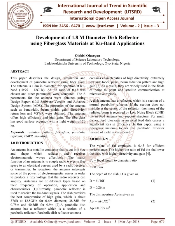
This paper describes the design, simulation and development of parabolic reflector using fiber glass. The antenna is 1.8m in diameter, for operation at Ku band 10.95 12GHz . An f d ratio of 0.43 was chosen and other parameters were computed. The S parameters for the antenna were obtained using Design Expert 6.0.8 Software Version and Advance Design System ADS . The properties of the antenna such as bandwidth, beam width, gain, directivity, return loss and VSWR were obtained. The antenna offers high efficiency and high gain. The fiberglass has good surface accuracy with a light weight of 20 kg. Olabisi Olusegun "Development of 1.8 M Diameter Dish Reflector using Fiberglass Materials at Ku-Band Applications" Published in International Journal of Trend in Scientific Research and Development (ijtsrd), ISSN: 2456-6470, Volume-2 | Issue-3 , April 2018, URL: https://www.ijtsrd.com/papers/ijtsrd11132.pdf Paper URL: http://www.ijtsrd.com/other-scientific-research-area/other/11132/development-of-18-m-diameter-dish-reflector-using-fiberglass-materials-at-ku-band-applications/olabisi-olusegun<br>

E N D
International Research Research and Development (IJTSRD) International Open Access Journal Development of 1.8 M Diameter Dish Reflector using Fiberglass Materials at Ku-Band Applications International Journal of Trend in Scientific Scientific (IJTSRD) International Open Access Journal ISSN No: 2456 ISSN No: 2456 - 6470 | www.ijtsrd.com | Volume 6470 | www.ijtsrd.com | Volume - 2 | Issue – 3 Development of 1.8 M Diameter Dish Reflector using Fiberglass Materials at Ku Development of 1.8 M Diameter Dish Reflector Band Applications Olabisi Olusegun Department of Department of Science Laboratory Technology, LadokeAkintola University of Technology, Oyo State, Nigeria LadokeAkintola University of Technology, Oyo State, Nigeria ABSTRACT This paper describes the design, simulation and development of parabolic reflector using fiber glass. The antenna is 1.8m in diameter, for operation at Ku band (10.95 – 12GHz). An f/d ratio of 0.43 was chosen and other parameters were computed. The S parameters for the antenna were obtained using Design-Expert 6.0.8 Software Version and Advance Design System (ADS). The properties of the antenna such as bandwidth, beam width, gain, directivity, return loss and VSWR were obtained. offers high efficiency and high gain. The fiberglass has good surface accuracy with a light weight of 20 kg. This paper describes the design, simulation and development of parabolic reflector using fiber glass. diameter, for operation at Ku- 12GHz). An f/d ratio of 0.43 was chosen and other parameters were computed. The S parameters for the antenna were obtained using Expert 6.0.8 Software Version and Advance contains characteristics of high directivity, extremely low side lobes, pencil beam radiation pattern and high gain [3].As a result, they are widely used in the fields of point to point and satellite communication at contains characteristics of high directivity, extremely low side lobes, pencil beam radiation gain [3].As a result, they are widely used in the fields of point to point and satellite communication at microwave regions. A dish antenna has a reflector, which is a section of a normal parabolic reflector. If the section does not include at the center of the reflector, then none of the radiated beam is received by Low Noise Block (LNB) the in feed antenna and support structure. For small dishes, feed blockage in an axial feed dish causes a significant loss in efficiency. In this paper, using a fiberglass material to for the parabolic reflector A dish antenna has a reflector, which is a section of a normal parabolic reflector. If the section does not include at the center of the reflector, then none of the radiated beam is received by Low Noise Block (LNB) the in feed antenna and support structure. For small dishes, feed blockage in an axial feed dish causes a significant loss in efficiency. In this pa fiberglass material to for the parabolic reflector instead of metal is considered. instead of metal is considered. s of the antenna width, gain, directivity, return loss and VSWR were obtained. The antenna offers high efficiency and high gain. The fiberglass has good surface accuracy with a light weight of 20 Keywords: radiation pattern, fiberglass, parabolic reflector, VSWR, moulding fiberglass, parabolic 2.0 DESIGN 1.0 INTRODUCTION The value of f/d employed is 0.43 for efficient performance. The higher the ratio of f/d the shallower The value of f/d employed is 0.43 for efficient performance. The higher the ratio of f/d the shallower the dish, with higher directivity and gain [4] the dish, with higher directivity and gain [4]. An antenna is a metallic conductor that is cut into size and shape which radiates electromagnetic waves function of an antenna is to couple radio waves in space to an electrical current used by a or transmitter. In reception, the antenna intercepts some of the power of electromagnetic waves in order to produce a tiny voltage that the radio receiver can amplify. Antennas are of different types based on their frequency of operation, application and characteristics [1].Currently, parabolic reflector is used to receive the ku-band signals. The dish provides the best compromise of high gain, which is about 37dB at 12.5GHz for 0.6m diameter, 38. 0.75m and 40.3dB for 0.9m [2].A parabolic dish antenna has a reflector which is a section of a parabolic reflector. Parabolic dish reflector antenna parabolic reflector. Parabolic dish reflector antenna An antenna is a metallic conductor that is cut into size and shape which radiates and and receives receives effectively. The major effectively. The major f/d = focal length to diameter ratio f/d = focal length to diameter ratio function of an antenna is to couple radio waves in free radio receiver f = 0.77m or transmitter. In reception, the antenna intercepts some of the power of electromagnetic waves in order to produce a tiny voltage that the radio receiver can The depth of the dish, D is given as The depth of the dish, D is given as D = d2/16f (1) ypes based on operation, application and D = 0.26 m characteristics [1].Currently, parabolic reflector is band signals. The dish provides the best compromise of high gain, which is about 37dB at 12.5GHz for 0.6m diameter, 38.5dB for 0.75m and 40.3dB for 0.9m [2].A parabolic dish antenna has a reflector which is a section of a The dish aperture Ap is given as The dish aperture Ap is given as Ap = π(d/2)? (2) Ap = 0.785 m2 @ IJTSRD | Available Online @ www.ijtsrd.com @ IJTSRD | Available Online @ www.ijtsrd.com | Volume – 2 | Issue – 3 | Mar-Apr 2018 Apr 2018 Page: 679
International Journal of Trend in Scientific Research and Development (IJTSRD) ISSN: 2456-6470 Return loss = -20log|ρ| (9) The wavelength (π) is λ =?? RL= -20 dB ? (3) 3.0 MATERIALS λ = 0.027 m Table 1: Formulation of a standard fiber glass moulding [7] Composition Polyester resin Fiber mat Filler Pigment Grease Catalyst 4.0 RESULTS AND DISCUSSION The E-field and H-field are given by [5] Percentage Content 30 18 48 3 0.6 0.3 jkr jke E 1 ( cos )( fxCos fySin ) 4 r (4) jkr jke E 1 ( cos )( fxSin fyCos ) 4 r (5) The parabolic reflector gain, G is given by [6] G=(4πϵ GP AP)/λ? (6) The simulation of the parameters for the antenna was done using Design Expert software (6.8.0) design System, Fig. 1 Shows the radiation pattern side lobes in polar form; Fig.2 and Fig.3 Shows the E- and H- Gain and Directivity, and Fig. 4 Shows the Return loss of fiberglass parabolic antenna. The antenna resonates at 10 GHz at a return loss of -20 dB with directivity and gain of 25 dB. G = 40.6 dB The reflection coefficient ρ is given as Z Z A 0 Z Z (7) A 0 ZA = Antenna Impedance Zo = Characteristics Impedance ρ= 0.04961 The voltage standing wave ratio is given as 1 P (8) VSWR 1 P VSWR = 130 ` Fig. 1 Shows the3-D radiation pattern with side lobes in polar form The return loss is given as Fig. 2 Shows the E- Gain and Directivity @ IJTSRD | Available Online @ www.ijtsrd.com | Volume – 2 | Issue – 3 | Mar-Apr 2018 Page: 680
International Journal of Trend in Scientific Research and Development (IJTSRD) ISSN: 2456-6470 Fig 3 Shows the H-Gain and Directivity Fig 4. Shows the Return loss Fig 5. Shows the VSWR 5.0 CONCLUSION In this paper, a fiberglass parabolic reflector antenna has been presented. The antenna has been designed to operate at (10.95 – 12GHz) in the Ku-band. The antenna has good pattern and proper .The design has been accomplished using commercially available Design-Expert 6.0.8 Software Versionand Advance Design System (ADS) with multiple interface. The design antenna has shown good performance in terms of return loss, VWSR and radiation patterns. The percentage compositions of materials required for @ IJTSRD | Available Online @ www.ijtsrd.com | Volume – 2 | Issue – 3 | Mar-Apr 2018 Page: 681
International Journal of Trend in Scientific Research and Development (IJTSRD) ISSN: 2456-6470 moulding of the antenna have also been presented. Good performance has been obtained for the envisaged applications. 2012, Institute minutes- Telecom and springer- verlag2012,27 April 2012. 5.T. Sivapriya and T. Nizhanthi, “A study on the effects of Rain Attenuation for an X- Band satellite System over Malaysia”, Progress in Electromagnetic Research B, 2012, 45: 37-56. 6.T.F Lai, W.N.L Mahadi and N. Soin” Circular Patch Microstrip Array Antenna for Ku-Band”, World Academy of Science,Engineering and Technology,2008,48: 298-302. 7.M. Gerard and B. communication System, System, Techniques, and Technologies”, Willey, Book, 5th edition, John Willey and sons Ltd, 2009. ACKNOWLEDGEMENTS Theauthor sincerely appreciate the contribution of the communication physics LadokeAkintola university of technology Ogbomoso, Nigeria for the release of GSP-730 spectrum analyser. research group of Michel, “ satellite REFERENCES 1.M.O Alade and O. Olabisi, “Development of microstrip patch antenna for Terrestrial indoor TV Reception” International Journal of Advanced Research in Electrical Instrumentation Engineering, 2013, 2(6): 2727- 2735 2.J.H.A Jadal, “Effect of rain on Ku-Band satellite system” International Journal of Electrical and Electronics Engineering, 2015, 4(2): 13-23. 3.A.H Aghvami and I. Robertson, “Power Limitation and High- nonlinearities in communication systems” Journal of Electronic Communication Engineering, 1993, 5(2): 65-70 4.N. Ranuka, I. Widad, and J.S Mandeep “ Rain- induced attenuation Communication in the west coast of Peninsular Malaysia, Penang”, Ann. Telecommunication, AUTHOR BIOGRAPHY Electronics and Olabisi Olusegun, he received his first degree in pure and applied physics (Electronic Option) in 2002 from Ladoke Akintola University Ogbomoso, Nigeria. In 2008, he graduated with distinction M.Tech in Electronics and Communication Physics from the same institution in 2008. He obtained PhD in Electronics Communication Option in 2015. He is a senior lecturer in the department of laboratory technology in Lautech, Nigeria. His research interests include; design, construction and analysis of antenna and electronic devices, and radio wave propagation. of Technology, Power –board amplifier satellite on for Ku-Band Satellite @ IJTSRD | Available Online @ www.ijtsrd.com | Volume – 2 | Issue – 3 | Mar-Apr 2018 Page: 682