Hemispherical Confocal Imaging using Turtleback Reflector
ACCV2010. Hemispherical Confocal Imaging using Turtleback Reflector. Yasuhiro Mukaigawa (Osaka University) Seiichi Tagawa (Osaka University) Jaewon Kim (MIT Media Lab) Ramesh Raskar (MIT Media Lab) Yasuyuki Matsushita (Microsoft Research Asia) Yasushi Yagi (Osaka University).

Hemispherical Confocal Imaging using Turtleback Reflector
E N D
Presentation Transcript
ACCV2010 Hemispherical Confocal Imaging using Turtleback Reflector Yasuhiro Mukaigawa (Osaka University) Seiichi Tagawa (Osaka University) Jaewon Kim (MIT Media Lab) Ramesh Raskar (MIT Media Lab) Yasuyuki Matsushita (Microsoft Research Asia) Yasushi Yagi (Osaka University)
Motivation • Clear view of a particular depth in the scene • Reduction of undesirable phenomena such as Occlusion Scattering [Vaish et al. CVPR2004] [Fuchs et al. EGSR2008]
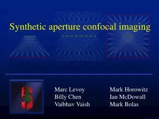
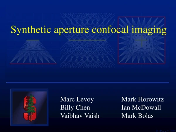
Related works [Levoy et al. SIGGRAPH2004] source Synthetic aperture Confocal imaging Normal view detector Problems: • Limited aperture size • Scattering Synthetic aperture confocal imaging
Our idea:Hemispherical confocal imaging Optical device • Specially designed polyhedral mirror • Synthesis of huge aperture • Pattern projection from many projectors • Focused illumination & descattering Image analysis
Huge aperture • Hemispherical aperture • does not exist • how to realize? • Advantages of huge aperture • extremely shallow DOF • clear view of the particular depth ? DOF Aperture size Small Large Huge F-number: 0 FOV: 180 [degree]
Hemispherical synthetic aperture • Synthetic aperture technique • many cameras on a hemisphere • uniform distance and density • problems: cost and physical conflict • Virtual cameras using planar mirrors Real camera Virtual cameras Target object Planar mirrors
Design of polyhedral mirror Virtual cameras Projection onto the ellipsoid Geodesic dome Hemisphere Target object Ellipsoid Real camera
Turtleback reflector View from a real camera Simulation by POV-Ray
How to make turtleback reflector First-surface mirror Cut Grind Plastic frame Planar mirrors Turtleback reflector (cost: 50US$)
Overview of the imaging system Projector Turtleback reflector Camera Beam splitter
Preliminary experiment (1) • Hemispherical synthetic aperture Orange mesh 2mm Textured paper 12 48 # of camera 1 3 Large Hemisphere Small Aperture
Preliminary experiment (2) • Covered by yellow dense mesh ... Large Hemisphere Small 2400x2000
Decomposition • Undesired phenomena • reflection from unfocused depth • scattering • Eliminate undesired components Blurred mesh Direct reflection from the focused depth Light source Eliminate Reflection from unfocused depth Special illumination using Turtleback reflector Scattering Focused depth
Special illumination Focused illumination High frequency illumination Illuminate the particular depth Separate direct / global components [Nayar et al. 2006] [Levoy et al. 2004] New idea: Focused High Frequency Illumination (FHFI) High frequency patterns are focused only on the particular depth
Focused High Frequency Illumination • Projection of high frequency positive and negative patterns • blurred in unfocused region • constant scattering Positive pattern Negative pattern Max – Min Positive 1 1/2 1/2 Negative 0 1/2 1/2 Max-Mix 1 0 0 Focused Eliminated Unfocused Scattering
Experimental results of FHFI • Covered by orange mesh • Covered by diffuse sheet FHFI Normal illumination Hemispherical aperture FHFI + Hemispherical aperture Normal illumination FHFI (descattering)
Position of our method • Limitations • The resolutions of virtual cameras and projectors are low. • The observable area is narrow. unfocused depth scanning scattering Synthetic aperture Confocal imaging Synthetic aperture confocal imaging Confocal imaging with descattering Hemispherical confocal imaging bright darken unilluminated darken unilluminated unnecessary necessary unnecessary necessary unnecessary remaining remaining partially reduced reduced reduced
Conclusion • Hemispherical confocal imaging to see a clear view of the particular depth • Hemispherical synthetic aperture by designing Turtleback reflector • Clear view of the particular depth by FHFI Future works: evaluation, application Factorization (skipped) (1) (2) (3)
Factorization • Dark regions due to absorption and occlusion • Factorization into three terms B A C absorption occlusion Camera A Camera B Camera C x x = Observed views Masking terms Reducing terms Texture term
Experimental result of Factorization FHFI + Hemispherical aperture Observed views from virtual cameras = x x ... ... ... Reducing terms Observed views Masking terms Texture term
Factorization = X texture observation X masking attenuation
Design of Turtleback reflector • Virtual cameras and projectors on the nodes of a geodesic dome • Circumscribed polyhedron to ellipsoid 75mm 90mm 100mm
Turtleback reflector • 50 first-surface mirrors • Plastic base by Stereolithography
A B C D 2mm Captured image transparent sheet printed paper 2000x1600