Download
1 / 4
40 likes | 64 Views
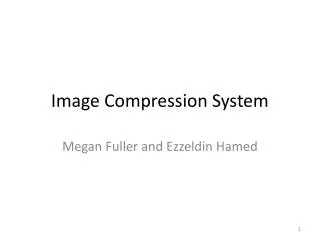
This paper deals with experimental investigation to calculate the value of main components of vapor compression refrigeration system and experimental results by using three different length of the capillary tube. At present, there are many types of refrigeration systems but the most widely used is vapor compression refrigeration system. This system is mainly used in air conditioning in buildings, electronic materials, automobile air conditioners, freezers, household refrigerators and even in supermarkets. This lab based refrigeration system is used R 134a because it can be replaced successfully for R 12 refrigerant and useful for many applications now. Moreover, it can be handling safely and has no damage effect to ozone layer. Ko Ko | Khin Maung Than | Aye Aye San "Design Calculation of Lab Based Vapour Compression System" Published in International Journal of Trend in Scientific Research and Development (ijtsrd), ISSN: 2456-6470, Volume-3 | Issue-6 , October 2019, URL: https://www.ijtsrd.com/papers/ijtsrd29213.pdf Paper URL: https://www.ijtsrd.com/engineering/mechanical-engineering/29213/design-calculation-of-lab-based-vapour-compression-system/ko-ko

E N D
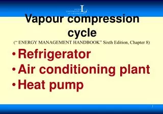
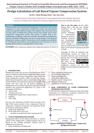
International Journal of Trend in Scientific Research and Development (IJTSRD) Volume 3 Issue 6, October 2019 Available Online: www.ijtsrd.com e-ISSN: 2456 – 6470 Design Calculation of Lab Based Vapour Compression System Ko Ko1, Khin Maung Than1, Aye Aye San2 1Assistant Lecturer, Mechanical Department, Technological University, Meiktila, Myanmar 2Lecturer, EI Department, Myanmar Aerospace Engineering University, Meiktila, Myanmar ABSTRACT This paper deals with experimental investigation to calculate the value of main components of vapor compression refrigeration system and experimental results by using three different length of the capillary tube. At present, there are many types of refrigeration systems but the most widely used is vapor compression refrigeration system. This system is mainly used in air- conditioning in buildings, electronic materials, automobile air-conditioners, freezers, household refrigerators and even in supermarkets. This lab based refrigeration system is used R-134a because it can be replaced successfully for R-12 refrigerant and useful for many applications now. Moreover, it can be handling safely and has no damage effect to ozone layer. KEYWORDS: main components, capillary tube, refrigeration systems, R-134a, R-12 How to cite this paper: Ko Ko | Khin Maung Than | Aye Aye San "Design Calculation of Lab Based Vapour Compression System" Published in International Journal of Trend in Scientific Research and Development (ijtsrd), ISSN: 2456- 6470, Volume-3 | Issue-6, October 2019, pp.693-696, URL: https://www.ijtsrd.com/papers/ijtsrd29 213.pdf Copyright © 2019 by author(s) and International Journal of Trend in Scientific Research and Development Journal. This is an Open Access article distributed under the terms of the Creative Commons Attribution License (http://creativecommons.org/licenses/b y/4.0) IJTSRD29213 (CC BY 4.0) 1.INTRODUCTION Refrigeration means the process of removing heat from a space to another by reducing the temperature under control condition. In this process, refrigerant is used. There are many refrigeration systems which are used for various applications. Among them, vapour compression refrigeration system (VCRS) is one of the most important of refrigeration system and now used for all general purposes of refrigeration such as industrial purposes especially for small domestic and commercial applications [1]. Some of the advantages of VCRS are: A. Size is small. B. Running cost is low. C.Refrigeration temperature can get easily as D.required. E.COP is high. But one of the drawbacks of VCRS is that its initial cost is high. VCRS consists mainly of four components. They are compressor, condenser, evaporator and expansion device. Each of these components should: A.Adapt to the application B.Be the right size for the work C. Function as needed with other components [2]. 2.TYPE OF REFRIGERATION SYSTEMS Refrigeration effect can be achieved by direct or indirect contact of the cooling with a cooling medium such as ice. Based on the working principle, common types of refrigeration systems are: ?Vapor Compression refrigeration ?Vapor absorption refrigeration ?Gas throttling refrigeration ?Steam jet refrigeration ?Vortex tube refrigeration ?Thermo acoustic refrigeration ?Magnetic refrigeration ?Liquefaction of natural gases [3]. 3.MAIN COMPONENTS OF VAPOR COMPRESSION REFRIGERATION SYSTEM For this lab based refrigeration system, four types of essential components are; compressor, condenser, evaporator and expansion device or metering device. Figure1. Mechanism of Simple Vapor Compression Refrigeration System @ IJTSRD | Unique Paper ID – IJTSRD29213 | Volume – 3 | Issue – 6 | September - October 2019 Page 693
International Journal of Trend in Scientific Research and Development (IJTSRD) @ www.ijtsrd.com eISSN: 2456-6470 A.Compressor The low pressure and temperature vapor refrigerant of the evaporator is passed through an inlet valve to the compressor where it is compressed at high temperature and high pressure. This high temperature and pressure refrigerant is sent to the condenser through an outlet or relief valve. In this experiment, hermetic type reciprocating compressor is used because it has less noise and not need much space. B.Condenser The condenser has copper tubes in which the vapor refrigerant of high pressure and temperature is cooled. Although the refrigerant passes through the condenser, it releases the latent heat of water or air to the surrounding condensation environment. Condenser must have good airflow while operation is running. C.Evaporator It consists of tubing that vaporizes the low pressure, low temperature liquid vapor coolant and converts it to low pressure and low temperature refrigerant vapor. After evaporation, the liquid coolant absorbs its latent heat of vaporization of the cooling medium. D.Expansion device The purpose of the expansion device or throttle valve is to allow the liquid refrigerant under high pressure and temperature to pass at a controlled rate as its pressure and temperature are reduced. When refrigerant has passed, it is evaporated and the residue is vaporized in the evaporator at low temperature and pressure [4,5]. 4.WORKING PROCESS IN A VAPOR COMPRESSION REFRIGERATION SYSTEM In a vapor compression refrigeration system, there are four major thermal processes taking place, namely; compression, condensation, expansion and evaporation. In all practical applications, VCRC is actually lower than the ideal cycle because of several factors such as friction losses, heat exchanges between parts of the system and pressure drop in the suction and discharge lines. 4.1.Pressure-Enthalpy Diagram Process 1-2 At first, VCRS is start from the compressor. In accordance with state point 1, the refrigerant in the form of a mixture of liquid and vapor enters the compressor, where isentropic compression is carried out. The compression process increases the refrigerant temperature from the lower limit to the upper limit. Work is introduced into the system and after compression the vapor becomes wet or saturated, but does not superheated. Process 2-3 In the form of vapor, the refrigerant enters the condenser at state 2, and the heat is removed under constant pressure and temperature. Once it exits the condenser, the refrigerant is saturated with liquid at point 3. Process 3-4 The refrigerant at point 3 of the state entering the expansion cylinder expands isentropically, and the temperature at the end of the expansion process drops to be lower. The work is obtained in the process of expansion. Process 4-1 The liquid refrigerant in state point 4 removes heat at a constant pressure and temperature from the space or material that is introduced into the evaporator and cooled, thereby producing a refrigeration effect [6]. 4.2.Pressure-Entropy Diagram Figure3. Pressure-Entropy Diagram for a Typical Refrigeration Cycle In the T-s diagram, QH and QL are heat flows and Win is the work input to the compressor. The rate of work input to the compressor is mainly the power required to operate the refrigeration system. Power may be required to drive one or more fans, but the power is low compared to compressor consumption. QH is the high temperature heat that the condenser rejects to the surroundings. QL is the low temperature heat absorbed from the space cooled by the evaporator [7]. Figure2. Pressure-Enthalpy Diagram for a Typical Refrigeration Cycle @ IJTSRD | Unique Paper ID – IJTSRD29213 | Volume – 3 | Issue – 6 | September - October 2019 Page 694
International Journal of Trend in Scientific Research and Development (IJTSRD) @ www.ijtsrd.com eISSN: 2456-6470 5.LAYOUT OF LAB BASED REFRIGERATION SYSTEM Specific enthalpies at the inlet and outlet of the expansion valve are equal, therefore 3 4 h = h 6.5.Coefficient of Performance (COP) Coefficient of Performance is the ratio between energy usage of the compressor and the amount of useful cooling at the evaporator. ( ) ( ) com 2 1 W h - h Where, 1 h= specific enthalpy of the evaporator outlet, kJ/kg 6.6. Volumetric Effect of Refrigerant h - h v 7.DESIGN SPECIFICATIONS OF VAPOR COMPRESSION SYSTEM Based on the different lengths of capillary tube, main components of operating parameters such as compressor work, refrigeration efficiency, mass flow rate of refrigerant, energy destruction in various components and COP are calculated. The values of enthalpies are obtained by using CoolPack software. 7.1.Design Calculation of Vapor Compression for 0.914 m Expansion Valve aP = h - h Q 1 4 eva COP = = (5) Figure4. Layout Design of Lab Based Refrigeration System 6.DESIGN CONSIDERATION OF VAPOR COMPRESSION REFRIGERATION SYSTEM 6.1.Mass Flow Rate of the Refrigerant V m v Where, m= mass flow rate of the refrigerant, kg/s V= volumetric flow rate at compressor inlet, m3/s 1 v= specific volume at compressor inlet, m3/kg 6.2.Heat Absorption by the Evaporator The refrigerant of heat absorbed by the liquid-vapour refrigerant is • r 4 eva 1 Q = m (h -h ) Where, Q = heat absorbed by the condenser, kW Volumetric effect = 1 4 (6) 1 = • r 1 (1) 1 • r 1 1P= suction pressure = 137.8951 kPa dP = Compressor displacement, Compressor speed, N = 3000 rpm Volumetric flow rate, = 4.6 × 10⁻⁴ m3/s The enthalpies and the specific volume can be obtained from pressure-enthalpy chart as the below. 2P= delivery pressure = 2516.5862 kPa (2) = 9.2 × 10⁻⁶ m3/rev D com D × N 1v = c eva 1 h= specific enthalpy of the evaporator outlet, kJ/kg h 6.3.Work done of the Compressor The work done during the isentropic compression of compressor is • r 2 com 1 W = m (h -h ) Where, W = workdone of the compressor, kW = specific enthalpy of the evaporator inlet, kJ/kg 4 (3) com 1 h= specific enthalpy of the condenser inlet, kJ/kg h 6.4.Heat Rejected by the Condenser Heat Rejected in the Condenser, = specific enthalpy of the condenser outlet, kJ/kg 2 Q is c 1 h = 400 kJ/kg h = 465 kJ/kg h= 297.75 kJ/kg • r Q Where, Q = m (h -h ) (4) con 2 3 2 3 h = 1v= 0.148 m3/kg 4 = heat rejected by the condenser, kW con @ IJTSRD | Unique Paper ID – IJTSRD29213 | Volume – 3 | Issue – 6 | September - October 2019 Page 695
International Journal of Trend in Scientific Research and Development (IJTSRD) @ www.ijtsrd.com eISSN: 2456-6470 Table4.1 Result datas for capillary tube length 0.914 m No. Description Symbols 1 Mass flow rate Power input to the compressor Heat absorption by the evaporator Heat rejected by the condenser Coefficient of performance 6 Volumetric effect 7.2.Design Calculation of Vapour Compression for 1.524 m Expansion Valve aP = Values 0.003 Units Kg/s • r m W 2 0.195 kW com Q 3 0.306 kW eva Q 4 0.501 kW con 1 h= 396.705 kJ/kg h= 462.5 kJ/kg h= 287.5 kJ/kg 5 COP 1.569 - - 690.878 kJ/m3 2 3 h = 1v= 0.2 m3/kg Table.3 Result datas for capillary tube length 2.134 m No. Description 1 Mass flow rate Power input to the compressor Heat absorption by the evaporator Heat rejected by the condenser Coefficient of performance 6 Volumetric effect By the comparison of three result tables, the best coefficient of performance is at capillary tube length of 0.914 m. The operating condition is not good for more than fifteen minutes and the compressor does not operate suddenly. If the length of the capillary tube is 2.134 m and the operating time is more than thirty minutes, the suction pressure and discharge pressure are in an unsteady state. By the comparison of three running condition, 2.134 m long of capillary tube is the best. 8.CONCLUSION This lab based refrigeration system is simple and easy to maintain. It can be used for laboratory experiments of basic refrigeration processes and principles of each component. It is fairly inexpensive so suitable for mechanical engineering students. Other researcher should test this system with different capacity of main components and refrigerants. RRFERENCES [1]http://www.engineering.myindialist.com/2009/vapor- compression-refrigeration/ #.XYjRrX8VTIV [2]A. R. Trott and T. Welch: "Refrigeration and Air- Conditioning", Third Edition, (2000) [3]Shan Wang: "Handbook of Air Conditioning System and Refrigeration", (2000) [4]R. S. Khurmi and J. K. Gupta, "A Textbook of Refrigeration and Air Conditioning", Revised Edition [5]William C. Whitman, William M. Johnson, John A. Tomczyk, Eugene Silberstein: "Refrigeration & Air Conditioning Technology", Seventh Edition, (2013) [6]https://www.brighthubengineering.com/hvac/35435- principles-of-the-vapor-compression-refrigeration- system/ [7]https://www.brighthubengineering.com/hvac/35435- principles-of-the-vapor-compression-refrigeration- system/ 4 1P= suction pressure = 96.5265 kPa dP = The enthalpies and the specific volume can be obtained from pressure – enthalpy chart as the below. 2P= delivery pressure = 2413.1648 kPa Symbols Values • r m Units Kg/s 0.0023 W 2 0.151 kW com Q 3 0.251 kW eva Q 4 0.403 kW con 5 COP 1.662 - - 546.02 kJ/m3 1 h = 390.14 kJ/kg h = 464.875 kJ/kg h = 306.35 kJ/kg 2 3 h = 1v = 0.22 m3/kg 4 Table 4.2 Result datas for capillary tube length 1.524 m No. Description 1 Mass flow rate Power input to the compressor Heat absorption by the evaporator Heat rejected by the condenser Coefficient of performance 6 Volumetric effect 7.3.Design Calculation of Vapour Compression for 2.134 m of Expansion Valve aP = Symbols m Values 0.002 Units Kg/s • r W 2 0.149 kW com Q 3 0.167 kW eva Q 4 0.317 kW con 5 COP 1.121 - - 380.864 kJ/m3 1P= suction pressure = 110.3157 kPa dP = The enthalpies and the specific volume can be obtained from pressure – enthalpy chart as the below. 2P = delivery pressure = 2585.5337 kPa @ IJTSRD | Unique Paper ID – IJTSRD29213 | Volume – 3 | Issue – 6 | September - October 2019 Page 696