Download
1 / 7
80 likes | 112 Views
The corrosion of steel reinforcement in concrete reduces the life of structures, causes high repair costs and can endanger the structural integrity of the structure itself. Glass fibre reinforced polymer GFRP offers a number of advantages over steel especially when used in marine and other salt laden environments. GFRP reinforcing bars are gradually finding wider acceptance as a replacement for conventional steel reinforcement as it offers a number of advantages. Technical studies on a number of concrete structures, from five to eight years old and constructed with GFRP reinforcement, have shown that there is no degradation of the GFRP from the alkaline environment. Concrete is very strong in compression but it is extremely weak in tension. To resist the tensile stress, steel reinforcement is provided in concrete. Reinforcement corrosion and structural deterioration in reinforced concrete structures are common, and prompted many researchers to seek alternative materials and rehabilitation techniques. One such material that has been offered as an alternative to mild steel reinforcement is Glass Fibre Reinforced Polymer GFRP bars and flats. For the repair and strengthening of structural concrete members, strengthening with Glass Fibre Reinforced Polymer GFRP plates is an excellent option. The present work is to study the behavior of Shear resistance of the silica coated GFRP stirrups in the shear test zone. A series of studies were conducted using silica coated GFRP stirrups in shear zone. It is observed that beams with silica coated GFRP flats shear reinforcement have shown failure at higher loads than the theoretical failure loads. Further it is observed that GFRP flats as shear reinforcement exhibit fairly good ductility. Er. Satish Kumar | Mr. Ajit Singh ""Behaviour of Glass Fiber Reinforced Polymer Composite in Flexure Shear Strength of Reinforced Concrete Beams"" Published in International Journal of Trend in Scientific Research and Development (ijtsrd), ISSN: 2456-6470, Volume-4 | Issue-3 , April 2020, URL: https://www.ijtsrd.com/papers/ijtsrd30440.pdf<br>Paper Url :https://www.ijtsrd.com/engineering/civil-engineering/30440/behaviour-of-glass-fiber-reinforced-polymer-composite-in-flexure-shear-strength-of-reinforced-concrete-beams/er-satish-kumar<br>

E N D
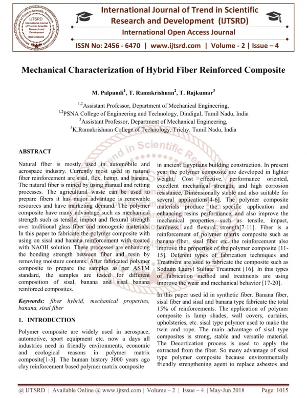
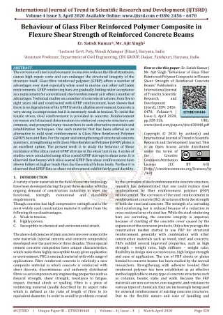
International Journal of Trend in Scientific Research and Development (IJTSRD) Volume 4 Issue 3, April 2020 Available Online: www.ijtsrd.com e-ISSN: 2456 – 6470 Behaviour of Glass Fiber Reinforced Polymer Composite in Flexure Shear Strength of Reinforced Concrete Beams Er. Satish Kumar1, Mr. Ajit Singh2 1Lecturer Govt. Poly, Mandi Adampur (Hisar), Haryana, India 2Assistant Professor, Department of Civil Engineering, CBS GROUP, Jhajjar, Fatehpuri, Haryana, India ABSTRACT The corrosion of steel reinforcement in concrete reduces the life of structures, causes high repair costs and can endanger the structural integrity of the structure itself. Glass fibre reinforced polymer (GFRP) offers a number of advantages over steel especially when used in marine and other salt laden environments. GFRP reinforcing bars are gradually finding wider acceptance as a replacement for conventional steel reinforcement as it offers a number of advantages. Technical studies on a number of concrete structures, from five to eight years old and constructed with GFRP reinforcement, have shown that there is no degradation of the GFRP from the alkaline environment. Concrete is very strong in compression but it is extremely weak in tension. To resist the tensile stress, steel reinforcement is provided in concrete. Reinforcement corrosion and structural deterioration in reinforced concrete structures are common, and prompted many researchers to seek alternative materials and rehabilitation techniques. One such material that has been offered as an alternative to mild steel reinforcement is Glass Fibre Reinforced Polymer (GFRP) bars and flats. For the repair and strengthening of structural concrete members, strengthening with Glass Fibre Reinforced Polymer (GFRP) plates is an excellent option. The present work is to study the behavior of Shear resistance of the silica coated GFRP stirrups in the shear test zone. A series of studies were conducted using silica coated GFRP stirrups in shear zone. It is observed that beams with silica coated GFRP flats shear reinforcement have shown failure at higher loads than the theoretical failure loads. Further it is observed that GFRP flats as shear reinforcement exhibit fairly good ductility. 1.INTRODUCTION A variety of new materials in the field of concrete technology have been developed during the past three decades with the ongoing demand of construction industries to meet the functional, strength, economical and durability requirements. Though concrete has high compressive strength and is the most widely used construction material it suffers from the following three disadvantages. A.Weak in tension. B.Highly porous. C.Susceptible to chemical and environmental attack. The above deficiencies of plain concrete are over-come in the new materials (special cements and concrete composites) developed over the past two or three decades. These special cement concrete composites have unique characteristics, which make them highly susceptible to any given application or environment. FRC is one such material with wide range of applications. Fibre reinforced concrete is relatively a new composite material in which concrete is reinforced with short discrete, discontinuous and uniformly distributed fibres so as to improve many engineering properties such as flexural strength, shear strength, resistance to fatigue, impact, thermal shock or spalling. Fibre is a piece of reinforcing material usually described by its aspect ratio which is defined as the ratio of length of fibre to its equivalent diameter. In order to avoid he problems created How to cite this paper: Er. Satish Kumar | Mr. Ajit Singh "Behaviour of Glass Fiber Reinforced Polymer Composite in Flexure Shear Strength of Reinforced Concrete Beams" Published in International Journal of Trend in Scientific Research and Development (ijtsrd), ISSN: 2456- 6470, Volume-4 | Issue-3, April 2020, pp.320-326, www.ijtsrd.com/papers/ijtsrd30440.pdf Copyright © 2020 by author(s) and International Journal of Trend in Scientific Research and Development Journal. This is an Open Access article distributed under the terms of the Creative Commons Attribution License (CC (http://creativecommons.org/licenses/by /4.0) IJTSRD30440 URL: BY 4.0) by the corrosion of steel reinforcement in concrete structure, research has demonstrated that one could replace steel reinforcement by fiber reinforcement polymer (FRP) reinforcement. The corrosion of the steel reinforcement in reinforcement concrete (RC) structures affects the strength of both the steel and concrete. The strength of a corroding steel reinforcing bar is reduced because of a reduction in cross sectional area of a steel bar. While the steel reinforcing bars are corroding, the concrete integrity is impaired, because of cracking of the concrete cover caused by the expansion of the corrosion products. Only a few year ago, the construction market started to use FRP for structural reinforcement, generally with combination with other construction materials such as wood, steel and concrete. FRPs exhibit several improved properties, such as high strength – weight ratio, high stiffness – weight ratio, flexibility in design non-corrosiveness, high fatigue strength and ease of application. The use of FRP sheets or plates bonded to concrete beams has been studied by the several researchers. Strengthening with adhesive bonded fiber reinforced polymer has been established as an effective method applicable to many type of concrete structures such as columns, beams, slabs and walls. Because the FRP materials are non-corrosive, non-magnetic, and resistance to various types of chemicals, they are increasingly being used for external reinforcement of existing concrete structures. Due to the flexible nature and ease of handling and @ IJTSRD | Unique Paper ID – IJTSRD30440 | Volume – 4 | Issue – 3 | March-April 2020 Page 320
International Journal of Trend in Scientific Research and Development (IJTSRD) @ www.ijtsrd.com eISSN: 2456-6470 application, combined with the high tensile strength – weight ratio and stiffness, the flexible glass fiber sheets are found to be highly effective for improve the strength of R.C beams. FRP can be used very efficiently in strengthening the concrete beams which weak in flexure, shear and torsion. FRP materials offer the engineer an outstanding combination of physical and mechanical properties, such as high tensile strength, lightweight, high stiffness, high fatigue strength and excellent durability. FRP is a composite material generally consisting of high strength carbon, agamid or glass fibers in a polymeric matrix (e.g. thermosetting resin) where the fibers are the main load carrying element. 2.LITERATURE REVIEW An et al. An et al. (1991) developed a model to predict the stresses and forces of a reinforced concrete beam with externally applied glass fiber reinforced plastics (GFRP). Their study was based on five assumptions: 1) linear strain distribution throughout the beam; 2) small deformations; 3) tensile strength of concrete was ignored; 4) shear deformation was ignored; 5) perfect bond between concrete and GFRP. Using classical flexural theory and strain compatibility, effects of variables such as material strength, modulus of elasticity, and reinforcement ratios of the steel and GFRP were compared with experimental results of a previous test (Saadatmanesh & Ehsani, 1991). The behavior of the beams were predicted with reasonable accuracy using the model. 1.Kavita Kene, et al conducted experimental study on behavior of steel and glass Fiber Reinforced Concrete Composites. The study conducted on Fiber Reinforced concrete with steel fibers of 0% and 0.5% volume fraction and alkali resistant glass fibers containing 0% and 25% by weight of cement of 12 mm cut length, compared the result. 2.G. Jyothi Kumari, et al studied behavior of concrete beams reinforced with glass fiber reinforced polymer flats and observed that beams with silica coated Glass fiber reinforced polymer (GFRP) flats shear reinforcement have shown failure at higher loads. Further they observed that GFRP flats as shear reinforcement exhibit fairly good ductility. The strength of the composites, flats or bars depends upon the fiber orientation and fiber to matrix ratio while higher the fiber content higher the higher the tensile strength. 3.Dr. P. Srinivasa Rao, et al conducted durability studies on glass fiber reinforced concrete. The alkali resistant glass fibers were used to find out workability, resistance of concrete due to acids, sulphate and rapid chloride permeability test of M30, M40 and M50 grade of glass fiber reinforced concrete and ordinary concrete. The durability of concrete was increased by adding alkali resistant glass fibers in the concrete. The experimental study showed that addition of glass fibers in concrete gives a reduction in bleeding. The addition of glass fibers had shown improvement in the resistance of concrete to the attack of acids. 4.S. H. Alsayed, et al studied the performance of glass fiber reinforced plastic bars as reinforcing material for concrete structures. The study revealed that the flexural capacity of concrete beams reinforced by GFRP bars can be accurately estimated using the ultimate design theory. The study also revealed that as GFRP bars have low modulus of elasticity, deflection criteria may control the design of intermediate and long beams reinforced with FDRP bars. 3.MATERIALS CONCRETE Concrete is a mixture of cement (11%), fine aggregates (26%), Coarse aggregates (41%) and water (16%) and air (6%) Cement →Powder Cement + Water → Cement Paste Cement Paste + Fine Aggregate (FA) → Mortar Mortar + Coarse Aggregate (CA) → Concrete Portland cement, water, sand, and coarse aggregate are proportioned and mixed to produce concrete suited to the particular job for which it is intended. CEMENT Portland cements are hydraulic cements, meaning they react and harden chemically with the addition of water. Cement contains limestone, clay, cement rock and iron ore blended and heated to 1200 to 1500 C°. The resulting product "clinker" is then ground to the consistency of powder. Gypsum is added to control setting time. FINE AGGREGATE Normally called sand, this component can be natural sand or crushed stone, and represents particles smaller than 4.75mm. Generally accounts for 30%-35% of the mixture. COARSE AGGREGATE May be either gravel or crushed stone. Makes up 40% -45% of the mixture, comprised of particles greater than 4.75mm. Water Water is an important ingredient of concrete as it actively participate in the chemical reactions with cement. Since it help to form the strength giving cement gel, the quantity and quality of water is required to be looked into very carefully. In practice, very often great control on properties of cement and aggregate is exercised, but the control on the quality of water is often neglected. Since quality of water affects the strength, it is necessary for us to go into the purity and quality of water. REINFORCEMENT Reinforced concrete is one of the most widely used modern building materials. Concrete is an “artificial stone” obtained by mixing cement, sand, and aggregates with water. Fresh concrete can be molded into almost any shape, giving it an inherent advantage over other materials. It became very popular after the invention of Portland cement in the 19th century; however, its limited tension resistance initially prevented its wide use in building construction. To overcome poor tensile strength, steel bars are embedded in concrete to form a composite material called reinforced concrete (RC). The use of RC construction in the modern world stems from the wide availability of its ingredients – reinforcing steel as well as concrete. FIBER REINFORCED POLYMER (FRP) Fibre-reinforced polymer (FRP), also Fibre-reinforced plastic, is a composite material made of a polymer matrix reinforced with fibres. The fibres are usually glass, carbon, or aramid, although other fibres such as paper or wood or asbestos have been sometimes used. The polymer is usually an epoxy, vinyl ester or polyester thermosetting plastic, and @ IJTSRD | Unique Paper ID – IJTSRD30440 | Volume – 4 | Issue – 3 | March-April 2020 Page 321
International Journal of Trend in Scientific Research and Development (IJTSRD) @ www.ijtsrd.com eISSN: 2456-6470 phenol formaldehyde resins are still in use. FRPs are commonly used in the aerospace, automotive, marine, and construction industries. 4.RESULTS The experimental results of SET I beams (weak in flexure) and SET II beams (weak in shear). Their behavior throughout the static test to failure is described using recorded data on deflection behavior and the ultimate load carrying capacity. The crack patterns and the mode of failure of each beam are also described in this chapter. Two sets of beams were tested for their ultimate strengths. In SET I three beams (BF1, BF2 and BF3) weak in flexure are tested. In SET II three beams (BS1, BS2 and BS3) weak in shear are tested. The beams BF1 and BS1 were taken as the control beams. It was observed that the beams BF1 and BF1 had less load carrying capacity when compared to that of the externally strengthened beams using GFRP sheets. In SET I beams BF2 is strengthened only at the soffit of the beam and BF3 is strengthened up to the neutral axis of the beam along with the soffit of the beam. SET II beams BS2 is strengthened only at the sides of the beam in the shear zone and BS3 is strengthened by U-wrapping of the GFRP sheets in the shear zone of the beam. Deflection behavior and the ultimate load carrying capacity of the beams were noted. The ultimate load carrying capacity of all the beams along with the nature of failure. FAILURE MODES The flexural and shear strength of a section depends on the controlling failure mode. The following flexural and shear failure modes should be investigated for an FRP- strengthened section: ?Crushing of the concrete in compression before yielding Sr. No. of the reinforcing steel; ?Yielding of the steel in tension followed by rupture of the FRP laminate; ?Yielding of the steel in tension followed by concrete crushing; ?Shear/tension delamination of the concrete cover (cover delamination); and ?Debonding of the FRP from the concrete substrate (FRP debonding). A number of failure modes have been observed in the experiments of RC beams strengthened in flexure and shear by GFRPs. These include flexure failure, shear failure, flexural failure due to GFRP rupture and crushing of concrete at the top. Concrete crushing is assumed to occur if the compressive strain in the concrete reaches its maximum usable strain. The GFRP strengthened beam and the control beams were tested to find out their ultimate load carrying capacity. It was found that the control beams BF1 and BS1 failed in flexure and shear showing that the beams were deficient in flexure and shear respectively. In SET I beam BF2 failed due to fracture of GFRP sheet in two pieces and then flexural-shear failure of the beam took place. Beam BF3 failed due to delamination of the GFRP sheet after that fracture of GFRP sheet took place and then flexural-shear failure of the beam. In SET I beams BF2 and BF3, GFRP rupture and flexural-shear kind of failure was prominent when strengthening was done using both the wrapping schemes. In SET II beams BF2 and BF3 failed due to flexural failure and crushing of concrete on the top of the beam. The SET II beams BF2 and BF3 developed major flexural cracks at the ultimate loads. In SET II beams BS2 and BS3 the flexural kind of failure was prominent when strengthening was done using both the wrapping schemes, Beam designation BF1 BF2 BF3 BSI BS2 BS3 Load at initial crack (KN) 32 41 Not visible 40 45 47 Ultimate Load (KN) 80 110 121 93 125 143 Type of Beam Nature of failure Flexural failure Beams weak in flexure (SET I) 1 GFRP rupture + Flexure-shear Failure GFRP rupture + Flexure-shear Failure Shear failure Crushing of Concrete Flexural failure + Crushing of Concrete Beams weak in shear (SET II) 2 Table 5.1 Ultimate load and nature of failure for SET I and SET II beams LOAD DEFLECTION TEST Load vs Deflection Curves for Beams BF1, BF2, & BF3 @ IJTSRD | Unique Paper ID – IJTSRD30440 | Volume – 4 | Issue – 3 | March-April 2020 Page 322
International Journal of Trend in Scientific Research and Development (IJTSRD) @ www.ijtsrd.com eISSN: 2456-6470 From the load and deflection of data of SET I beams F1, F2 and F3, load vs deflection curve is plotted for all the three beams. From this load vs deflection curve, it is clear that beam F1 has lower ultimate load carrying capacity compared to beams F2 and F3. Beam F1 had also undergone higher deflection compared to beams F2 and F3 at the same load. Beam F2 had higher ultimate load carrying capacity compared to the controlled beam F1 but lower than beam F3. Beam F3 had higher ultimate load carrying capacity compared to the beams F1 and F2. Both the beams F2 and F3 had undergone almost same deflection upto 73 KN load. After 73 KN load beam F3 had undergone same deflection as beam F2 but at a higher load compared to beam F2. The deflection undergone by beam F3 is highest. Beam F2 had undergone higher deflection than beam F1. Load vs Deflection Curves for Beams BS1, BS2 & BS3 From the load and deflection of data of SET II beams BS1, BS2 and BS3, load vs deflection curve is plotted for all the three beams. From this load vs deflection curve, it is clear that beam BS1 has lower ultimate load carrying capacity compared to beams BS2 and BS3. Beam BS1 had also undergone higher deflection compared to beams BS2 and BS3 at the same load. Beam BS2 had higher ultimate load carrying capacity compared to the controlled beam BS1 but lower than beam BS3. Beam BS3 had higher ultimate load carrying capacity compared to the beams BS1 and BS2. Both the beams BS2 and BS3 had undergone almost same deflection upto 82 KN load. After 82 KN load beam BS3 had undergone same deflection as beam BS2 but at a higher load compared to beam BS2. The deflection undergone by beam BS3 is highest. Beam BS2 had undergone higher deflection than beam BS1. LOAD AT INITIAL CRACK Two point static loading was done on both SET I and SET II beams and at the each increment of the load, deflection and crack development were observed. T he load at initial crack of all the beams was observed, recorded Fig.5.9 Load at initial crack of beams BF1, BF2 & BF3 Set – 1 Beams Details BF1: Control Beam BF2: Strength only at the soffit of the Beam BF3: Strength at the soffit and upto the neutral axis of the Beam Under two point static loading of SET I beams, at each increment of load, deflection and crack development were observed. In beam BF1 initiation of the crack takes place at a load of 32 KN which is lower than beam BF2 in which crack initiation started at 41 KN. The crack initiation of beam BF3 was not visible due to application of GFRP sheet up to the neutral axis of the beam. The cracks were only visible after a load of 90 KN. @ IJTSRD | Unique Paper ID – IJTSRD30440 | Volume – 4 | Issue – 3 | March-April 2020 Page 323
International Journal of Trend in Scientific Research and Development (IJTSRD) @ www.ijtsrd.com eISSN: 2456-6470 Fig.5.10 Load at initial crack of beams BS1, BS2 and BS3 Set – 1 Beams Details BS1: Control Beam BS2: Strength only at the sides of the beam in shear zone BS3: Strength at the U- wrapping of the beam in shear zone Under two point static loading of SET II beams, at each increment of load, deflection and crack development were observed. In beam BS1 initiation of the crack takes place at a load of45 KN which is low er than beam BF2 in which crack initiation started at 49 KN an further lower than beam BF3 in which crack initiation started at 50 KN. The re was not much difference in load for crack initiation in beam BS2 and BS3. ULTIMATE LOAD CARRYING CAPACITY The load carrying c capacity of the control beams and the strengthen beams were found out. The control beams were l loaded up to their ultimate loads. It was noted that of all the beams, the strengthen beams BF2, BF3 and BS2, BS3 had the higher load carrying capacity compared to the controlled beams BF1 and BS1. An important character to be noticed about the usage of GFRP sheets is the high ductile behaviour of the beams. The shear failure being sudden can lead to huge damage to the structure. But the ductile behaviour obtained by the use of GFRP can give us enough warning before the ultimate failure. The use of FRP can delay the initial cracks and further development of the cracks in the beam. Fig.5.11 Ultimate load of beams BF1, BF2 and BF3 Set – 1 Beams Details BF1: Control Beam BF2: Strength only at the soffit of the Beam BF3: Strength at the soffit and up to the neutral axis of the Beam SET I beams BF1, BF2 and BF3 were loaded under two point static loading. As the load was increased incrementally development of cracks takes place and ultimately the beam failed. The ultimate load of BF1 beam was 80 KN which is lower than BF2 beam which carried an ultimate load of 110 KN and further lower than BF3 beam which carried an ultimate load of 121 KN. @ IJTSRD | Unique Paper ID – IJTSRD30440 | Volume – 4 | Issue – 3 | March-April 2020 Page 324
International Journal of Trend in Scientific Research and Development (IJTSRD) @ www.ijtsrd.com eISSN: 2456-6470 Ultimate load of beams BS1, BS2 and BS3 Set – 1 Beams Details BS1: Control Beam BS2: Strength only at the sides of the beam in shear zone BS3: Strength at the U- wrapping of the beam in shear zone SET II beams BS1, BS2 and BS3 were loaded under two point static loading. As the load was increased incrementally development of cracks takes place and ultimately the beam failed. The ultimate load of BS1 beam was 93 KN which is lower than BS2 beam which carried an ultimate load of 125 KN and further lower than BS3 beam which carried an ultimate load of 143 KN. CRACK PATTERN The crack patterns at collapse for the tested beams of SET I and SET II are shown in Fig. 5.13 to 5.18. In SET I the controlled beam BF1 exhibited widely spaced and lesser number of cracks compared to strengthened beams BF2 and BF3. The strengthened beams BF2 and BF3 have also shown cracks at relatively close spacing. This shows the enhanced concrete confinement due to the GFRP strengthening. This composite action has resulted in shifting of failure mode from flexural failure (steel yielding) in case of controlled beam BF2 to peeling of GFRP sheet in case of strengthened beams BF2 and BF3. The debonding of GFRP sheet has taken place due to flexural-shear cracks by giving cracking sound. A crack normally initiates in the vertical direction and as the load increases it moves in inclined direction due to the combined effect of shear and flexure. If the load is increased further, cracks propagate to top and the beam splits. This type of failure is called flexure-shear failure. 5.CONCLUSIONS From the test results and calculated strength values, the following conclusions are drawn: A.SET I Beams (BF1, BF2 and BF3) 1.Initial flexural cracks appear at a higher load by strengthening the beam at soffit. The ultimate load carrying capacity of the strengthen beam BF2 is 37% more than the controlled beam BF1. 2.Load at initial cracks is further increased by strengthening the beam at the soffit as well as on the two sides of the beam up to the neutral axis from the soffit. The ultimate load carrying capacity of the strengthen beam BF3 is 51 % more than the controlled beam BF1 and 10 % more than the strengthen beam BF2. 3.Analytical analysis is also carried out to find the ultimate moment carrying capacity and compared with the experimental results. It was found that analytical analysis predicts lower value than the experimental findings. 4.When the beam is not strengthen, it failed in flexure but after strengthening the beam in flexure, then flexure- shear failure of the beam takes place which is more dangerous than the flexural failure of the beam as it does not give much warning before failure. Therefore it is recommended to check the shear strength of the beam and carry out shear strengthening along with flexural strengthening if required. 5.Flexural strengthening up to the neutral axis of the beam increases the ultimate load carrying capacity, but the cracks developed were not visible up to a higher load. Due to invisibility of the initial cracks, it gives less warning compared to the beams strengthen only at the soffit of the beam. 6.By strengthening up to the neutral axis of the beam, increase in the ultimate load carrying capacity of the beam is not significant and cost involvement is almost three times compared to the beam strengthen by GFRP sheet at the soffit only. B.SET II Beams (BS1, BS2 and BS3) 1.The control beam BS1 failed in shear as it was made intentionally weak in shear. 2.The initial cracks in the strengthen beams BS2 and BS3 appears at higher load compared to the un-strengthen beam BS1. 3.After strengthening the shear zone of the beam the initial cracks appears at the flexural zone of the beam and the crack widens and propagates towards the neutral axis with increase of the load. The final failure is flexural failure which indicates that the GFRP sheets increase the shear strength of the beam. The ultimate load carrying capacity of the strengthen beam BS2 is 34 % more than the controlled beam BS1. 4.When the beam is strengthen by U-wrapping in the @ IJTSRD | Unique Paper ID – IJTSRD30440 | Volume – 4 | Issue – 3 | March-April 2020 Page 325
International Journal of Trend in Scientific Research and Development (IJTSRD) @ www.ijtsrd.com eISSN: 2456-6470 [4]Applications. Focusing on Innovation, Technology Implementation and Sustainability. Springer 2012. shear zone, the ultimate load carrying capacity is increased by 53 % compared to the control beam BS1 and by 14% compared the beam BS2 strengthen by bonding the GFRP sheets on the vertical sides alone in the shear zone of the beam. 5.When the beam is strengthen in shear, then only flexural failure takes place which gives sufficient warning compared to the brittle shear failure which is catastrophic failure of beams. 6.The bonding between GFRP sheet and the concrete is intact up to the failure of the beam which clearly indicates the composite action due to GFRP sheet. 7.Restoring or upgrading the shear strength of beams using GFRP sheet can result in increased shear strength and stiffness with no visible shear cracks. Restoring the shear strength of beams using GFRP is a highly effective technique. 6.REFERENCES [1]Hinton M. J., Soden P. D., Kaddour A. S. Failure Criteria in Fibre-Reinforced-Polymer Composites: The World- Wide Failure Exercise. Elsevier 2004. [5]Kimg Hwee TAN. Fibre Reinforced Polymer. Reinforcement for Concrete Structures. Proceedings of the Sixth International Symposium on FRP Concrete Structures, volume 1-2 (FRPRCS-6). World Scientific 2003. [6]Erki M. A., and Rizkalla S. H. FRP Reinforcement for Concrete Structures. Concrete International (1993) 48- 53. [7]Han E.H. Meijer, Govaert Leon E. Mechanical performance of polymer systems: The relation between structure and properties. Prog. Polym. Sci. 30 (2005) 915-938. [8]McGraw-Hill Science & Technology Encyclopedia [9]Entsiklopediia polimerov, vols. 1–3. Moscow, 1972-77. The Great Soviet Encyclopedia, 3rd Edition (1970- 1979). 2010 The Gale Group, Inc. 38 Fiber Reinforced Polymers - The Technology Applied for Concrete Repair [2]Tong L., Mouritz A. P., Bannister M. 3D Fibre Reinforced Polymer Composites. Elsevier 2002. [10]Giancaspro Balaguru P. Mechanical behavior of fire-resistant biocomposite. Composites: Part B 40 (2009) 206-211. James, Papakonstantinou Christos, [3]Ravi Jain, Luke lee. Fiber Reinforced Polymer (FRP) Composites for Infrastructure @ IJTSRD | Unique Paper ID – IJTSRD30440 | Volume – 4 | Issue – 3 | March-April 2020 Page 326