Understanding Electrical Earthing and Grounding Practices for Safety and Efficiency
530 likes | 696 Views
This document provides an overview of electrical earthing and grounding based on IEEE 80 standards. It illustrates the objectives of grounding, including the protection of electrical equipment, human safety, and providing a low impedance path for fault currents. Grounding practices are influenced by local regulations and are essential for ensuring the safety and functionality of electrical installations. Additionally, the text discusses various grounding methods, their benefits, and the mitigation of hazards associated with electrical faults. This is crucial for maintaining operational integrity and protecting against unexpected electrical failures.

Understanding Electrical Earthing and Grounding Practices for Safety and Efficiency
E N D
Presentation Transcript
Special Note: • The approach here is based on standard IEEE 80 (Safety in AC substation grounding) • These discussions are for illustration only • Grounding practices are subject to local regulations/codes which will take precedence
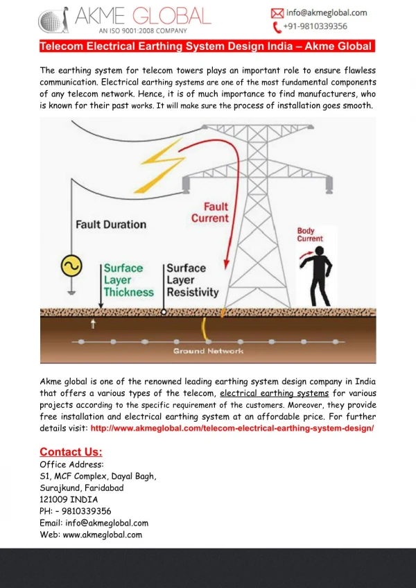
Objectives of grounding: • Provides an electrical supply system with a reference to the groundmass (system grounding) • Protective grounding of electrical equipment enclosures • Makes them safe to persons who may come into contact with them • Enables the flow of fault current in the event of a failure • Provides a low impedance path for accumulated static charges and surges (lightning protection grounding) • Helps in mitigating the generation and propagation of noise (grounding of shields and signal reference planes)
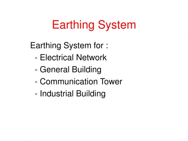
Earthing System Shall satisfy Safety, Functional requirements of electrical installation Shall ensure • Protection against indirect contact • Proper functioning of electrical protective devices • Protective and functional requirements are met under expected conditions • Earth fault, earth leakage currents can be carried safely • Adequate strength appropriate to external influences • Adequate value of earthing resistance
Benefits (1) • Fault damage now minimal • Reduces fire hazard (especially in mines) • Lower outage times • Less lost production, less lost revenue • Touch potentials kept within safe limits • Protects human life
Benefits (2) • Low Fault Currents reduce possibility of igniting gases • Minimizes explosion hazard • Lower Magnetic or thermal stresses imposed on plant during fault • Transient overvoltages limited • Prevents stressing of insulation, breaker restrikes
System grounding • Provides reference for the entire power system to groundmass • Establishes a path for current to ground during insulation failure • Provides protection against equipment damage due to faults • Provides protection against high voltage transients • Enables detection by circuit protective devices for isolation • Reduces maintenance time and expenditure
Fault in Ungrounded system • Single phase ground fault does not result in flow of high fault currents • Voltage to ground of other two phases rises by 73% - Causes insulation stress • Fault current = Vector sum of capacitive currents in the distributed capacitive reactance of other two phases
Fault in Ungrounded system • Intermittent first fault causes transient voltages up to 6 to 8 times nominal system voltage • Such high transient voltage can initiate a second fault at weakest insulation point • Uncleared arcing fault can cause extensive damage to system • Early detection of first fault therefore of paramount importance
Ungrounded System Neutral connection on Generator/ Transformer is not connected to earth at all Grounding methods 1
Grounding methods 2 Solid grounding • Neutral connection on Generator / Transformer is connected to earth by a solid Conductor • Cost Reductiuons due to avoidance of sensitive relays and grounding device, Grading of insulation towards neutral end. • But Circulation of third harmonic currents between neutrals
Grounding methods 3 • Resistance grounding • Neutral connection on Generator / Transformer is connected to earth (0V) through a fixed resistance to limit the earth fault current • Mainly used below 33 KV • Full line to line insulation required towards neutral
Grounding methods 4 • Reactance grounding • Neutral connection on Generator / transformer is connected to earth (0V) through a fixed reactance to limit the earth fault current • Can be cheaper compared to resistance
Grounding methods 5 • Petersen Coil grounding (arc suppression) • Neutral connection on transformer is connected to earth (0V) through a variable reactance to neutralise the capacitive earth fault current. Results in arc extinction
Grounding methods 6 • NEC grounding (with and without resistance) • In HV delta systems no earth connection is available. A 3 phase neutral grounding compensator is connected to allow earth fault currents to flow - allowing detection of these faults
Protective grounding • Protects personnel against shocks • Personnel do not experience dangerous high voltages when contacting enclosure accidentally connected to live parts • Provides a low impedance path for accumulated static charges and surges (lightning protection grounding) • Helps in mitigating the generation and propagation of noise (grounding of shields and signal reference planes)
Importance for Earthing • An Electrical equipment is considered dead when • At or about zero potential • Disconnected/ Isolated from live system • Disconnection alone not adequate • Can retain stored charge • Can acquire a static charge • Can accidentally be made alive • Nearby live conductors may induce voltage
Importance of Earthing • !Ensure earthing before working on electrical equipment • Earthing • Connect apparatus electrically to general mass of earth in such a manner as will ensure at all times an immediate safe discharge of electrical energy • Connect to earthed metal earth bar or spike with good metallic conductor • Earthing by • Closing of earthing links • Attaching of fixed earthing devices • Affixing of portable earthing straps
Importance of Earthing • Ensure before applying earth • Earthing connection is mechanically, electrically in good condition • No broken strands • Clamps should be rigid and without defect • Applied properly in intimate contact with conductors and earth-bar/ spike • Earthing cable tails as short as possible • Connect to earth first when installing earthing, disconnect earth last while removing earthing
Hazards of improper Earthing • Electrocution • Burns from arcing • Electric shock leading to falls
Bonding • Connecting of various grounding systems and non current carrying parts • To achieve potential equalization between different accessible conducting surfaces • Potential difference between different accessible conducting surfaces, different grounding systems hazardous
Touch Voltage Permissible Touch Voltage Voltage at any point of contact with uninsulated metal work • Within 2.5 mtrs from ground surface and • Any point on ground surface within horizontal distance of 1.25 mtrs from vertical projection of point of contact with uninsulated metal work
Step Voltage • Difference in surface potential experienced by a person bridging a distance of 1 mtr with his feet apart, without contacting any other earthed object • Shall not exceed twice the value of Touch voltage
Touch potentials (Reb =1 ) Person touches transformer tank now live
Touch potentials (Reb = 10 ) Lower touch potential
Transferred Potential Make Allowances for • Transferred potential during design, installation • Voltage drop in conductors (where voltage rise in earthing system is transferred by metal work to remote location) • Otherwise regard Transferred potential as earthing system voltage rise
Transferred Earth Potential Rise Earthing system shall be designed to prevent • Transfer of earth grid potentials to a remote earth • Transfer of a remote earth potential into a station • Breakdown of cable over-sheaths due to voltage differences
Substation grounding practices-1: • Grounding design approach depends upon: • Voltage class of the system • Type of installation (Utility or consumer) • LV Systems: • Usually solidly grounded • Metallic contact between ground of consumer and system neutral • Special cases such as SELV power supplies may be of ungrounded type
Substation grounding practices-2: • MV Systems: • Self contained systems (E.g., Turbo generators): High resistance grounding • Industrial systems: Low resistance • Critical systems: Tuned grounding OR Ungrounded (for small systems) • Utilities: Solid grounding • HV/EHV Systems: Solid grounding
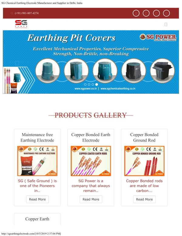
A typical ground electrode: Materials • Copper • Copper clad steel • Galvanized steel • Copper clad stainless steel
A typical chemical electrode: • Sometimes called a leach electrode • Chemical mixtures are added to lower resistance of soil • Needs regular maintenance
Area of ground grid: • HV (outdoor) substations use a buried ground grid for dissipation of fault current to the soil • Lower grid resistance to earth is preferable • It reduces the ground potential rise with ref. to remote earth • Also reduces mesh voltage. Lower mesh voltage is safer because it lowers touch/step voltages • Grid of larger area has lower ground resistance and results in lower grid voltage and mesh voltage • Further reduction by using vertical electrodes welded to the grid
Soil resistivity: • Soil resistivity should be based on an average of measurements done in the substation area • Simple designs assume uniform soil • Non uniform soil involves complex design steps and requires computer programs • Lower resistivity results in lower ground resistance of the grid
Other issues to be taken note of: • Soil layers may differ in resistivity • Two layer soil model to be considered if variations are found to be high at different depths • Transferred potential due to buried services going to/ from the substation (water mains, cable metallic sheath) • Introduce non-conducting sections where feasible to avoid transfer of Ground potential
Special attention to be paid to: • Operating handles of equipment: • Most fatalities occur due to high touch potential at these points • Should be made safe by special arrangements • Substation fence: • Decision regarding keeping isolated vs connecting to substation ground • Surge arrestors: • Short, direct and low impedance connections • GIS extensions
Effective substation grounding - 1: • Size ground conductors adequately • Use proper bonding and jointing in ground conductors. Poor joints cause high temperatures during a fault to ground • Select appropriate ground electrode system • Pay attention to soil resistivity. Carry out soil improvement if resistivity is too high. Use chemical electrodes if situation warrants
Effective substation grounding - 2: • Pay attention to step and touch potentials • Building foundations can also be used as grounding electrodes • Integrate fence of outdoor substations as far as possible. Avoid transferred potential from services entering or leaving a substation • Pay special attention to operating handles
Effective substation grounding - 3: • Cable trays to be properly grounded • Surge arrestors to be grounded using short low impedance connections • Carry out temporary grounding for safety when personnel have to work on parts which are normally live