Download
1 / 17
170 likes | 189 Views
This guide provides information on using a single and multi-tool method for cut through tasks, including the necessary parameters and specifications. It also includes compatibility information for different software and instructions on configuring the contour and cut through lines.

E N D
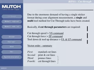
Due to the enormous demand of having a single sticker format during your alignment measurement, a single and multi tool method for Cut Through tasks have been created. Basically, 4 cut through parameters are required:Cut through speed > VS commandCut through force > ZF commandTool down & tool up distance > UL & LT command Vector order - summaryFirst: standard cut linesSecond: print & cut linesThird: pounce linesFourth: cut through lines
A sticker example containing contour paths&cut through paths Cut through line contour-path
Cut through specifications: reduce your speed, increase your force, use all pressure rollers, lower your cut through media width dimension, choose your in between margins for cut through stickers sufficient enough, minimal vinyl movement + plot order important (first → contour data, second → cut through data), 0° orientation, VS/ZF/AS menu = accept (new header per line type), easy cut through shapes (rectangles, circles, squares), NO multi-frame alignment systems advised (multi-segment), NO repeat mode recommend
For cut through reasons, it is better to have this dashing technique (intermittent plotting via the LT, UL commands) configured at the end of your vector data group. The sorting routine of your software should therefore automatically configure these vector paths at the end of your file output. Cut Through compatible alignments are: Two cut through methods can be applied: Method 1 – with one single tool Method 2 – multiple tools → tool 1: P&C lines → tool 2: cut through lines Cut Through
Software compatibilities for cut through tasks (16/02/2010) • EasySign: OK (single tool / multi tool method) • grip / grip+: OK (note: SC-PRO plotter ID not compatible) • SAintl: OK (plot setting / line color) • Onyx: NOK (SP command not included in vector file)
This single tool method will complete both contour and cut through data with one single knife holder Drag knife settings:Standard knife depth → cutting mat(= cut through depth)- contour lines: 110g - 60 cm/s- cut through lines: 250g - 10 cm/s standard holder = cut through holder Vinyl Glue Silicon Paper Cutting mat
This multi - tool method will complete both contour and cut through data with two separated knife holders Drag knife settings:Standard knife depth → silicon paperCut through knife depth →cutting mat- contour lines: 110g - 60 cm/s- cut through lines: 250g - 10 cm/s Standard holder cut through holder Vinyl Glue Silicon Paper Cutting mat
What to do?KONA menu option → Settings 3/4 - Swap Alert = single / multi tool (similar plot file – menu option decides its cut through method). Example: Plot file with SP2 included (SP = Select Pen)A message on panel will inform the user to swap tools accordingly (based on the SP parameter included) Please insert the Continue inThrough Cut tool and confirm OR Single tool mode Put the lever up to cancel Summary:SP1 = DEFAULT cut tool (preset) – print and cut vector pathsSP2 = THROUGH CUT tool (preset) – cut through vector paths SP3..8 = tool 3..8
[2] Grip / Grip (+) Note: SC-PRO driver can NOT be used (different ID number)
[4] ONYX - No cut through plotting yet integrated (next release?)
Important menu options – tips: - Swap Alert [Single tool, Multi tool]Used for cut through tasks – single or multi-tool method- VS/ZF/AS [Accept / Ignore]This menu setting allows the user to accept the cut through parameters- Trim Poster Confirm 4 registration marks on panel (via tool jogging)Result: Cut Through done of your poster (trimming) - Cut Through test patternVerify your Cut Through parameters on panel (only for test purposes)
Important menu options – tips: Loading modes – media detection: with front, without front, uneven media with front, uneven media without frontWith Front: Right, Left, Front, Load lengthWithout Front: Right, Left, Load length (origin location = current head location @ start)Uneven media with front: Right, Left, Front, Load length Uneven media without front: Right, Left, Load length (origin location = current head location @ start)