Download

1 / 17
190 likes | 445 Views
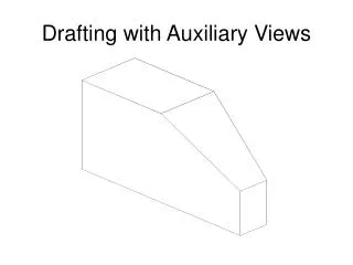
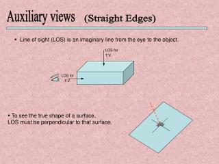
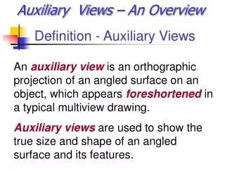
Auxiliary Views. Auxiliary Views. Auxiliary view Orthographic projection of an angled surface A ppears foreshortened in a typical multi-view drawing Auxiliary views are used to show true size and shape of angled surface features. Foreshortened Surfaces.

E N D
Auxiliary Views • Auxiliary view • Orthographic projection of an angled surface • Appears foreshortened in a typical multi-view drawing • Auxiliary views are used to show true size and shape of angled surface features
Foreshortened Surfaces • Foreshortened surfaces on multi-view drawings are unclear and inaccurate representation of size or shape • View should not be dimensioned Foreshortened Face
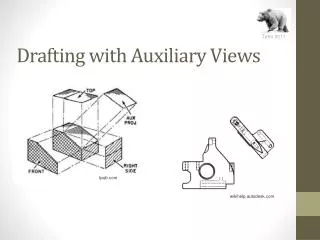
Foreshortened Surfaces • Auxiliary viewis perpendicular to an angled surface • Shows true size and shape of the surface features e.g., hole in surface as shown True Height Auxiliary Distance
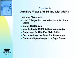
Types of Auxiliary Views • Three types of ordinary auxiliary views • Depth auxiliary • Height auxiliary • Width auxiliary
Types of Auxiliary Views • Depth auxiliary view derived from frontor back viewto show true depth • Width auxiliary view derived from sideviewto show true width • Height auxiliary view derived from topor bottom viewto show true height
Creating Auxiliary Views • Step #1 • Multi-view drawing containing canted surface • Example will be more clear with auxiliary view of canted surface on front view
1 2 4 1 5,6 3 5 4,7 6 9 7 2,9 3,8 8 1,2 1 2 3,4 4 3 5 5 7 8,7 8,9 6 6 9
Creating Auxiliary Views • Step #2 • Determine true dimension to show on auxiliary view • Identify reference edges on existing view • Draw appropriately spaced construction lines where auxiliary view will be drawn • Construction lines are reference lines parallel to angled edge
Edge View ofReference Plane Reference Line
Creating Auxiliary Views • Step #3 • Draw construction lines outward from each corner of view • Auxiliary view will be a 90° rotation of view • Lines must be perpendicular to angled edge • Identify relationship between object corners and construction line intersections
1 1 2 4 1 5,6 3 2 4 5 5 4,7 3 7 6 6 9 9 7 2,9 3,8 8 8 1,2 1 2 3,4 4 3 5 5 7 8,7 8,9 6 6 9
Creating Auxiliary Views • Step #4 • Draw object lines to connect corners that share a visible edge
1 1 2 4 1 5,6 3 2 4 5 5 4,7 3 7 6 6 9 9 7 2,9 3,8 8 8 1,2 1 2 3,4 4 3 5 5 7 8,7 8,9 6 6 9
Auxiliary view is projected from front view • Shows true size and true shape of the angled surface • If hole were located on surface, then it could be properly dimensioned
Partial Views • Foreshortened object faces can be difficult to draw because of complex shapes or curves • Short break lines and partial views simplify difficult curves on foreshortened faces while maintaining complete shape description
short break lines Partial Views