Download
1 / 21
210 likes | 306 Views
Learn about NGC Software for control processes and data acquisition, with features like clock pattern generation and synchronization.

E N D
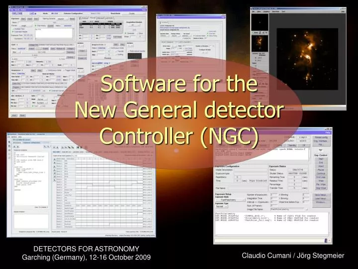
Software for the New General detector Controller (NGC) Claudio Cumani / Jörg Stegmeier
NGC System Overview NGC LLCU (Linux) 2 2 2 2 2 3 3 3 3 3 Down Down Down Down Down Down Down Down NGC LLCU (Linux) AQ AQ [N] - ADC [N] - ADC [N] - ADC [N] - ADC [N] - ADC [N] - ADC [N] - ADC Up Up Up Up Up Up Up FEB Detector 4 - ADC Clock/Bias Driver Up Sequencer Detector Shutter-Ctrl Preamp-Ctrl Detector Detector Detector Detector Detector Detector LLCU = Linux Local Control Unit
IWS (Linux) NGC LLCU (Linux) NGC LLCU (Linux) NGC Computing Architecture • Programming Language: • C++ for control processes • Tcl/Tk for GUI and Startup-Scripts Instrument LAN Fast Ethernet/ Gigabit-Ethernet … With the current Linux-PC model we can achieve 200 Mbytes/s sustained input data-rate with co-adding (double correlated read-out)
Goals • One software basis for both optical and infrared applications. • Maximum heritage of the strength of both IRACE (infrared predecessor) and FIERA (optical predecessor). • Modular object oriented architecture. • Configurable for all possible system realizations (i.e. number of ADC-modules, number of bias-generators etc.). • Easily programmable clock-pattern generation. • Synchronization with external events. • Version control and automated testing.
Data Commands The Processes Instrument Workstation Error-System GUI Log-System Database Config.-Files FITS-Files Control Server Command/ Reply Real-Time Display Data-Acquisition-Process (Pre-Processing, Sorting,…) Acquisition Process (Pre-Processing, Sorting,…) Driver-Interface-Process Device Driver PCI-Bus Interface NGC LLCU Fiber-Optic-Link to NGC Front End
NGC-DCS Control Server • The control server can be used as NGC-HW Control Sub-System of the NGC Optical Software (NGCOSW). That is the maximum degree of communality as the same compiled and linked object is used by both applications to access the HW. • It can be configured at Run-Time for the one or the other purpose. • This is also used as general Engineering Tool. Instrument Workstation Error-System GUI Log-System Database Config.-Files FITS-Files Control Server Command/ Reply Infrared Applications
Controller Programming • The detector voltages are defined in a Voltage Configuration File in Short-FITS format (xxx.v). • Clock-Pattern blocks can be defined both in ASCII-Format (xxx.clk) and in a Binary Format (xxx.bclk, output of the Graphical Editing Tool BlueWave). The formats can be converted automatically. • Synchronization with external events (e.g. trigger) can be done after any state in any clock-pattern block. • A Sequencer Programming Language has been defined to program the clock-pattern execution. • There may be Multiple Sequencer Instances within one detector front end system.
Clock-Pattern Generation • The clock pattern blocks define sequences of clock states, which are stored in a RAM inside the NGC sequencer hardware. • The bits in the RAM define the state of each physical clock line plus: • Some control bits (“wait-for-trigger”, “end-of-pattern”). • The duration of each state (dwell time) is defined in the state itself. • Patterns can be programmed via a graphical tool (Bluewave) PATRAM Pattern RAM High Pattern RAM Low … + 0: 00000000000001010001000000000000 00000000000000000000000000000000 State 1 … + 1: 00000000000001010001000000000001 00000000000000000000000000000100 State 2 … + 2: 00000000000001010001000000000001 00000000000000000000000000000100 State 3 : … +(n-1): 10000000000001010001000000000000 00000000000000000000000000000000 State n … + n: 00000000000001010001000000000000 00000000000000000000000000000000 State 1 … +(n+1): 00000000000001010001000000000001 00000000000000000000000000000100 State 2 … +(n+2): 00000000000001010001000000000001 00000000000000000000000000000100 State 3 : … +(n+m-1): 10000000000001010001000000000000 00000000000000000000000000000000 State m ^ ^ ^ ^ ^ ^ ^ ^ ^ ^ ^ ^ ^ ^ ^ ^ ^ 64 60 56 52 48 44 40 36 32 28 24 20 16 12 8 4 1 Clock Pattern 1 Pattern 2 End of Pattern
Sequencer Programming • The sequencer program defines the order of execution of the defined clock pattern blocks. • Simple 7-instruction code RAM. • Easy to be compiled. Address : Pattern-RAM HI Pattern-RAM LO BIT [31..0] BIT [31..0] PATRAM+ 0: PATRAM+ 1: PATRAM+ 2: PATRAM+ 3: PATRAM+ 4: PATRAM+ 5: PATRAM+ 6: PATRAM+ 7: PATRAM+ 8: PATRAM+ 9: PATRAM+10: PATRAM+11: PATRAM+12: PATRAM+13: PATRAM+14: PATRAM+15: PATRAM+16: PATRAM+17: PATRAM+18: : : Clock-Pattern Block 1 Clock-Pattern Block 2 Clock-Pattern Block 3 Clock-Pattern Block 4 Clock-Pattern Block 1 Clock-Pattern Block 2 Clock-Pattern Block 3 Clock-Pattern Block 4 Address : <Instruction> <Rep> <Address> BIT [30..28] [26..11] [10..0] SEQRAM+0: [LOOP] [N] [-] SEQRAM+1: [EXEC] [N] [PATRAM offset] SEQRAM+2: [LOOP] [N] [-] SEQRAM+3: [EXEC] [N] [PATRAM offset] SEQRAM+4: [LOOPEND] [-] [-] SEQRAM+5: [JSR] [-] [SEQRAM offset] SEQRAM+6: [LOOPEND] [-] [-] SEQRAM+7: [EXIT] [-] [-] : : … +offset : [EXEC] [N] [PATRAM offset] … +offset+1: [EXEC] [N] [PATRAM offset] … +offset+2: [RETURN] [-] [-] [LOOP] = 010 [JSR] = 101 [EXEC] = 001 [LOOPINF] = 100 [RETRUN] = 110 [EXIT] = 000 [LOOPEND] = 011
Sequencer Program Language • The sequencer program language is fully driven by Setup Parameters (e.g. detector integration time, number of integrations, window parameters, …). • Support of Arithmetic Expression Evaluation (TCL-syntax) to derive any program-loop parameter from the setup parametersand to compute attributes like exposure time estimation and minimum DIT. • Support of Sub-Routines and Include-Files to minimize the code length.
External Synchronization • Synchronization points can be inserted at any place in any clock pattern executed by the sequencer program (i.e. set the “wait-for-trigger” bit in the particular state). • When reaching such a point the pattern execution is suspended until the arrival of an external trigger signal.
Infrared “Exposures” • Sustained Detector Read-Out and Video Display (display remains active during the “Exposure”). • Sustained Data-Transfer between NGC-LLCU and Instrument Workstation for application specific Post-Processing (slow control loops, e.g. secondary auto-guiding). • Starting an “Exposure” basically means “starting to transfer data to disk”. • Burst-Mode for fast raw data acquisition.
Data Acquisiton Processes • Multi-threaded pre-processing framework. • High concurrency (receive, process, transfer to multiple readers, handle command). • One process per read-out mode guarantees maximum independency and maximum safety (cannot corrupt working code, releases all resources). • Template Processes have been developed, which are an easy-to-use and stand-alone tool to visualize NGC raw-data on the real-time display. • Standard acquisition processes for the ESO Standard IR Detectors (HAWAII 1Kx1K, HAWAII2-RG 2Kx2K, SELEX, AQUARIUS, …) are available within the NGC software package. Special setups (e.g. mosaics) may require special software modules.
Frame Types • User-definable Frame-Types (Raw-Sample, Mean-Value, Standard-Deviation, Half-Chop-Cycle, Intermediate Results…). • The types can be selected to be generated/stored during an exposure. • Exposure Break-Conditions can be set per “per frame-type”. • Individual SW-Windows per frame-type.
Data Interface • FITS-Files • Wait for exposure termination and read the generated FITS-file(s). • Direct connection to Acquisition Process (e.g. real-time display) • Retrieve the binary image data with just minimum header information (dimension, type, sequential number). • Post-Processing Call-Back • The control server calls a user-defined procedure before the frame is stored.
Optical vs. IF NGC • Active intervention of the control-server during the exposure is required (application of new voltages in each state “wiping”, “integrating”, “reading”). • “Active” interface to different kinds of shutter controllers (open/close, status check, open/close delays, etc.).
Finite State Machine Detector controllers can be modeled as finite state machines i.e.: model of behavior composed of a finite number of states, transitions between those states, and actions
State Machine - UML • Designed using UML (Unified Modeling Language) • From this model, code can be automatically generated!
wsf Code generation tool: ESO wsf - workstation software framework: • state design (described by a configuration file) • automatic code generation from state design “automatically generated” code handles state transitions, messages, commands, error conditions, etc. (NOT the actions needed to drive an exposure!) • implementation of detector control code (CCD, shutter, etc)
Results • Code dimension: • NGC Base-SW: 220000 lines of code (Test SW = 16 %) • NGC IR-SW: 36000 lines of code (Test SW = 12 %) • NGC Optical SW: 82000 lines of code (Test SW = 27 %) • Code dimension for optical NGC ~ code dimensions for FIERA controller • Automatically generated code for optical NGC is 78% of the total optical NGC code (without Test SW) • All NGC software modules are under version control and contain test procedures for automated testing according to the ESO VLT SOFTWARE standards.
Goals are achieved… • One software basis for both optical and infrared applications. • Maximum heritage of the strength of both IRACE (infrared predecessor) and FIERA (optical predecessor). • Modular object oriented architecture. • Configurable for all possible system realizations (i.e. number of ADC-modules, number of bias-generators etc.). • Easily programmable clock-pattern generation. • Synchronization with external events. • Version control and automated testing.