Download
1 / 21
210 likes | 358 Views
Software for the New General detector Controller (NGC). NGC System Overview. NGC LLCU (Linux). 2. 2. 2. 2. 2. 3. 3. 3. 3. 3. Down. Down. Down. Down. Down. Down. Down. Down. NGC LLCU (Linux). AQ. AQ. [N] - ADC. [N] - ADC. [N] - ADC. [N] - ADC. [N] - ADC.

E N D
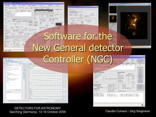
Software for the New General detector Controller (NGC) Claudio Cumani / Jörg Stegmeier
NGC System Overview NGC LLCU (Linux) 2 2 2 2 2 3 3 3 3 3 Down Down Down Down Down Down Down Down NGC LLCU (Linux) AQ AQ [N] - ADC [N] - ADC [N] - ADC [N] - ADC [N] - ADC [N] - ADC [N] - ADC Up Up Up Up Up Up Up FEB Detector 4 - ADC Clock/Bias Driver Up Sequencer Detector Shutter-Ctrl Preamp-Ctrl Detector Detector Detector Detector Detector Detector LLCU = Linux Local Control Unit
IWS (Linux) NGC LLCU (Linux) NGC LLCU (Linux) NGC Computing Architecture • Programming Language: • C++ for control processes • Tcl/Tk for GUI and Startup-Scripts Instrument LAN Fast Ethernet/ Gigabit-Ethernet … With the current Linux-PC model we can achieve 200 Mbytes/s sustained input data-rate with co-adding (double correlated read-out)
Goals • One software basis for both optical and infrared applications. • Maximum heritage of the strength of both IRACE (infrared predecessor) and FIERA (optical predecessor). • Modular object oriented architecture. • Configurable for all possible system realizations (i.e. number of ADC-modules, number of bias-generators etc.). • Easily programmable clock-pattern generation. • Synchronization with external events. • Version control and automated testing.
Data Commands The Processes Instrument Workstation Error-System GUI Log-System Database Config.-Files FITS-Files Control Server Command/ Reply Real-Time Display Data-Acquisition-Process (Pre-Processing, Sorting,…) Acquisition Process (Pre-Processing, Sorting,…) Driver-Interface-Process Device Driver PCI-Bus Interface NGC LLCU Fiber-Optic-Link to NGC Front End
NGC-DCS Control Server • The control server can be used as NGC-HW Control Sub-System of the NGC Optical Software (NGCOSW). That is the maximum degree of communality as the same compiled and linked object is used by both applications to access the HW. • It can be configured at Run-Time for the one or the other purpose. • This is also used as general Engineering Tool. Instrument Workstation Error-System GUI Log-System Database Config.-Files FITS-Files Control Server Command/ Reply Infrared Applications
Controller Programming • The detector voltages are defined in a Voltage Configuration File in Short-FITS format (xxx.v). • Clock-Pattern blocks can be defined both in ASCII-Format (xxx.clk) and in a Binary Format (xxx.bclk, output of the Graphical Editing Tool BlueWave). The formats can be converted automatically. • Synchronization with external events (e.g. trigger) can be done after any state in any clock-pattern block. • A Sequencer Programming Language has been defined to program the clock-pattern execution. • There may be Multiple Sequencer Instances within one detector front end system.
Clock-Pattern Generation • The clock pattern blocks define sequences of clock states, which are stored in a RAM inside the NGC sequencer hardware. • The bits in the RAM define the state of each physical clock line plus: • Some control bits (“wait-for-trigger”, “end-of-pattern”). • The duration of each state (dwell time) is defined in the state itself. • Patterns can be programmed via a graphical tool (Bluewave) PATRAM Pattern RAM High Pattern RAM Low … + 0: 00000000000001010001000000000000 00000000000000000000000000000000 State 1 … + 1: 00000000000001010001000000000001 00000000000000000000000000000100 State 2 … + 2: 00000000000001010001000000000001 00000000000000000000000000000100 State 3 : … +(n-1): 10000000000001010001000000000000 00000000000000000000000000000000 State n … + n: 00000000000001010001000000000000 00000000000000000000000000000000 State 1 … +(n+1): 00000000000001010001000000000001 00000000000000000000000000000100 State 2 … +(n+2): 00000000000001010001000000000001 00000000000000000000000000000100 State 3 : … +(n+m-1): 10000000000001010001000000000000 00000000000000000000000000000000 State m ^ ^ ^ ^ ^ ^ ^ ^ ^ ^ ^ ^ ^ ^ ^ ^ ^ 64 60 56 52 48 44 40 36 32 28 24 20 16 12 8 4 1 Clock Pattern 1 Pattern 2 End of Pattern
Sequencer Programming • The sequencer program defines the order of execution of the defined clock pattern blocks. • Simple 7-instruction code RAM. • Easy to be compiled. Address : Pattern-RAM HI Pattern-RAM LO BIT [31..0] BIT [31..0] PATRAM+ 0: PATRAM+ 1: PATRAM+ 2: PATRAM+ 3: PATRAM+ 4: PATRAM+ 5: PATRAM+ 6: PATRAM+ 7: PATRAM+ 8: PATRAM+ 9: PATRAM+10: PATRAM+11: PATRAM+12: PATRAM+13: PATRAM+14: PATRAM+15: PATRAM+16: PATRAM+17: PATRAM+18: : : Clock-Pattern Block 1 Clock-Pattern Block 2 Clock-Pattern Block 3 Clock-Pattern Block 4 Clock-Pattern Block 1 Clock-Pattern Block 2 Clock-Pattern Block 3 Clock-Pattern Block 4 Address : <Instruction> <Rep> <Address> BIT [30..28] [26..11] [10..0] SEQRAM+0: [LOOP] [N] [-] SEQRAM+1: [EXEC] [N] [PATRAM offset] SEQRAM+2: [LOOP] [N] [-] SEQRAM+3: [EXEC] [N] [PATRAM offset] SEQRAM+4: [LOOPEND] [-] [-] SEQRAM+5: [JSR] [-] [SEQRAM offset] SEQRAM+6: [LOOPEND] [-] [-] SEQRAM+7: [EXIT] [-] [-] : : … +offset : [EXEC] [N] [PATRAM offset] … +offset+1: [EXEC] [N] [PATRAM offset] … +offset+2: [RETURN] [-] [-] [LOOP] = 010 [JSR] = 101 [EXEC] = 001 [LOOPINF] = 100 [RETRUN] = 110 [EXIT] = 000 [LOOPEND] = 011
Sequencer Program Language • The sequencer program language is fully driven by Setup Parameters (e.g. detector integration time, number of integrations, window parameters, …). • Support of Arithmetic Expression Evaluation (TCL-syntax) to derive any program-loop parameter from the setup parametersand to compute attributes like exposure time estimation and minimum DIT. • Support of Sub-Routines and Include-Files to minimize the code length.
External Synchronization • Synchronization points can be inserted at any place in any clock pattern executed by the sequencer program (i.e. set the “wait-for-trigger” bit in the particular state). • When reaching such a point the pattern execution is suspended until the arrival of an external trigger signal.
Infrared “Exposures” • Sustained Detector Read-Out and Video Display (display remains active during the “Exposure”). • Sustained Data-Transfer between NGC-LLCU and Instrument Workstation for application specific Post-Processing (slow control loops, e.g. secondary auto-guiding). • Starting an “Exposure” basically means “starting to transfer data to disk”. • Burst-Mode for fast raw data acquisition.
Data Acquisiton Processes • Multi-threaded pre-processing framework. • High concurrency (receive, process, transfer to multiple readers, handle command). • One process per read-out mode guarantees maximum independency and maximum safety (cannot corrupt working code, releases all resources). • Template Processes have been developed, which are an easy-to-use and stand-alone tool to visualize NGC raw-data on the real-time display. • Standard acquisition processes for the ESO Standard IR Detectors (HAWAII 1Kx1K, HAWAII2-RG 2Kx2K, SELEX, AQUARIUS, …) are available within the NGC software package. Special setups (e.g. mosaics) may require special software modules.
Frame Types • User-definable Frame-Types (Raw-Sample, Mean-Value, Standard-Deviation, Half-Chop-Cycle, Intermediate Results…). • The types can be selected to be generated/stored during an exposure. • Exposure Break-Conditions can be set per “per frame-type”. • Individual SW-Windows per frame-type.
Data Interface • FITS-Files • Wait for exposure termination and read the generated FITS-file(s). • Direct connection to Acquisition Process (e.g. real-time display) • Retrieve the binary image data with just minimum header information (dimension, type, sequential number). • Post-Processing Call-Back • The control server calls a user-defined procedure before the frame is stored.
Optical vs. IF NGC • Active intervention of the control-server during the exposure is required (application of new voltages in each state “wiping”, “integrating”, “reading”). • “Active” interface to different kinds of shutter controllers (open/close, status check, open/close delays, etc.).
Finite State Machine Detector controllers can be modeled as finite state machines i.e.: model of behavior composed of a finite number of states, transitions between those states, and actions
State Machine - UML • Designed using UML (Unified Modeling Language) • From this model, code can be automatically generated!
wsf Code generation tool: ESO wsf - workstation software framework: • state design (described by a configuration file) • automatic code generation from state design “automatically generated” code handles state transitions, messages, commands, error conditions, etc. (NOT the actions needed to drive an exposure!) • implementation of detector control code (CCD, shutter, etc)
Results • Code dimension: • NGC Base-SW: 220000 lines of code (Test SW = 16 %) • NGC IR-SW: 36000 lines of code (Test SW = 12 %) • NGC Optical SW: 82000 lines of code (Test SW = 27 %) • Code dimension for optical NGC ~ code dimensions for FIERA controller • Automatically generated code for optical NGC is 78% of the total optical NGC code (without Test SW) • All NGC software modules are under version control and contain test procedures for automated testing according to the ESO VLT SOFTWARE standards.
Goals are achieved… • One software basis for both optical and infrared applications. • Maximum heritage of the strength of both IRACE (infrared predecessor) and FIERA (optical predecessor). • Modular object oriented architecture. • Configurable for all possible system realizations (i.e. number of ADC-modules, number of bias-generators etc.). • Easily programmable clock-pattern generation. • Synchronization with external events. • Version control and automated testing.