Download
1 / 22
220 likes | 407 Views
140kW, 94GHz Heavily Loaded TE 01 Gyro-TWT. D.B. McDermott, H.H. Song, Y. Hirata, A.T. Lin 1 , T.H. Chang 2 , K.R. Chu 2 and N.C. Luhmann, Jr. Department of Applied Science, UC Davis 1 Department of Physics, UCLA 2 Department of Physics, NTHU

E N D
140kW, 94GHz Heavily Loaded TE01 Gyro-TWT D.B. McDermott, H.H. Song, Y. Hirata, A.T. Lin1, T.H. Chang2, K.R. Chu2 and N.C. Luhmann, Jr. Department of Applied Science, UC Davis 1 Department of Physics, UCLA 2 Department of Physics, NTHU This work has been supported by AFOSR under Grants F49620-99-1-0297 (MURI-MVE) and F49620-00-1-0339.
Outline • Small-Signal Design for Stability • Wall Loss • Large-Signal Characteristics • Circuit Components
Motivation • Why Gyro-TWT? • Wider Bandwidth than Gyro-Klystron • Higher Circuit Efficiency Higher Power Capability • Why TE01 Mode? • Low Loss • Well Centered for MIG Electron Beam (Peaks for r/rw=0.5) • Azimuthal Symmetry is Favorable for MIG Beam • Field Pattern is Unique (Jz=0 and Er=0) • - Useful for Mode Selective Circuit
Dispersion Diagram - TE01 Gyro-TWT 100 kV, v^/vz=1.0 Must Suppress TE11(1) , TE21(1) and TE02(2) Gyro-BWO Interactions
Stable Beam Current (Absolute Instability at Cutoff) Beam Current can be Higher for Lower v^/vz and Lower Bo/Bg 100 kV, v^/vz=1.0 Unloaded TE01(1) Circuit is Stable for 5 A, v^/vz=1.0, and Bo/Bg=1.0
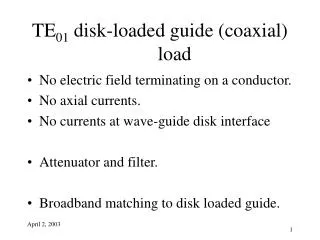
Gyro-BWO Stability in Lossy TE01(1) Circuit • Wall is Coated with Lossy Graphite to Suppress Gyro-BWO [ NTHU's Technique, PRL81, 4760 (1998)] • r/rcopper = 7.104 yields Stability and 100 dB Loss for 14.5 cm Circuit
Power Growth in Lossy Single-Stage DeviceSelf-Consistent Large-Signal Simulation Code CW Wall Loading < 50 W/cm2 • Large-Signal Gain = 50 dB • Efficiency = 28% • Peak Power = 140 kW 100 kV, 5 A, v^/vz =1 Dvz/vz = 5% • Electron efficiency is nearly independent of loss • Final 2.5 cm is unloaded to avoid damping high power wave 92.25 GHz
Predicted Saturated Bandwidth 5% Bandwidth is Predicted • Dw/w = 5% • Pout = 140 kW • h = 28% • Gain = 50 dB • rw = 2.01 mm • rc/rw = 0.45 • r/rcopper = 70,000 • Llossy = 11.0 cm • Lcopper = 2.5 cm • Lloss-taper = 1.0 cm • Lcircuit = 14.5 cm 7
Gyro-TWT Circuit has been Fabricated MIG Connection Input Coupler Interaction Region Output Coupler Collector 30 cm ruler Axial View
Gyro-TWT Circuit has been Fabricated Cross-Section of Coaxial Coupler Rectangular Input Waveguide Coaxial Cavity Interaction Circuit
0 dB TE01 Input Coupler Azimuthal Phase-Velocity Coupler • HFSS Design • Similar to • UCLA’s TE81 • Gyro-TWT Coupler • NRL’s Gyroklystron Coax Coupler • All Modes are Matched
TE51/TE01 Coax-Cavity Input Coupler TE10 Rectangular Waveguide intoTE51 Coax-Cavity into TE01 Circular Waveguide
RF Measurement Set-up for Coupler and Circuit Loss • MPI Flower-Petal TE10 / TE01 Transducers Give <1.3 VSWR over 5% Bandwidth • DURIP W-Band Vector Network Analyzer at SLAC will Measure Optimized Components Set-up for Coupler Measurement W-Band Scalar Network Analyzer 12
Bandwidth of Coaxial Input Coupler • Coupler exhibits > 2 dB coupling for 3% bandwidth • Performance is limited by cutoff of short Cutoff of short • Predicted for 93.0 - 96.5 GHz • Coupling > 1 dB • Selectivity > 40 dB • Return Loss (TE01) > 7 dB • Return Loss (TE21) > 14 dB • Return Loss (TE11) > 28 dB • Feature: No tapering is needed between coupler and gain region
Future Coaxial Input Coupler Although the initial Gyro-TWT experiment will employ the previous coaxial couplers, plans have been initiated to develop an improved coupler for future experiments. These three modifications of the original display a 7% bandwidth. 15
Measured Loss in Circuit Interaction Circuit has been Coated with Aquadag Aquadag is a Carbon Colloid with r/rCu=70,000 and dskin=0.06 mm Measurements versus HFSS Modeling 90 dB Loss Measured at 93 GHz
Single-Anode MIG (100 kV, 5 A, v^/vz = 1 • Designed with FINELGUN • Fabricated by NTHU • Mo Coating - Edge Emission • Cathode Angle 74o • Magnetic Compression 32 • Guiding Center Radius 0.9 mm • Cathode Radius 5.1 mm • Emitting Strip Length 1.9 mm • Guiding Center Spread 10% • Axial Velocity Spread 5% • Electric Field 70 kV • Cathode Loading 9 A/cm2 • Jemis/JL 0.3
MIG Has Been Activated Cathode Stalk Very Steep Cathode (74) Emitting Ring
Superconducting Magnet Profile • 50 kG ± 0.1% over 50 cm • Large 6" ID Bore • Refrigerated Field Profile of the Four Independent Coils
100W 94GHz TWT Input Driver Hughes 987 Coupled-Cavity TWT CPI 1kW EIO is Also Available
Summary • UCD 94GHz Gyro-TWT has been Constructed - Capable of 140kW with Dw/w=5% and h=28% • Circuit is Heavily Loaded to Suppress Gyro-BWO - Final 2.5 cm is Unloaded to Avoid Damping Saturated Wave - Loss has Negligible Effect on Efficiency - 90 dB Loss Measured at 93 GHz • MIG was Designed with Dvz/vz = 5% and v^/vz = 1.0 - MIG has been Activated • Coax Couplers were Designed with HFSS - Good Match for All Modes - Very Short Length (5 mm) - Input and Output Couplers have been Measured