MICROPROGRAMMED CONTROL CH 17
MICROPROGRAMMED CONTROL CH 17. Team # 2 Members: Wilmer Saint-Hilaire Alberto Mollinedo Vinicius Schuina Luis Perez. Microinstructions. Microprogramming Microinstruction Microprogram (Firmware). Horizontal Microinstruction. All the control unit does is generate a set of control signals

MICROPROGRAMMED CONTROL CH 17
E N D
Presentation Transcript
MICROPROGRAMMED CONTROL CH 17 Team # 2 Members: Wilmer Saint-Hilaire Alberto Mollinedo Vinicius Schuina Luis Perez
Microinstructions • Microprogramming • Microinstruction • Microprogram (Firmware)
Horizontal Microinstruction • All the control unit does is generate a set of control signals • Each control signal is on or off • Represent each control signal by a bit • Have a control word for each micro-operation • Have a sequence of control words for each machine code instruction • Add an address to specify the next micro-instruction, depending on conditions
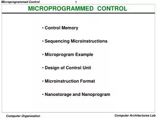
Control Unit Instruction Cycle • The set of microinstructions is stored in the Control Memory • Instruction Execution • Sequence logic unit issues a read command to the control memory. • The word whose address is specified in the control address register is read into the buffer control register. • Control buffer generates control signals, and sends the next address information to the sequencing logic unit. • Seq. logic unit load the new address into the control address register.
Vertical Microinstruction • In vertical microinstruction code is used for every action to be performed, such as: {MAR to PC}, and the decoder translates this code into individual code signals.
Advantages / Disadvantages • The use of microprogramming simplifies the design to implement a control unit. • Cheaper and less error prone to implement. • Somewhat slower than a hardwire unit of comparable technology.
Questions • Where does the Control Unit get the address for the next microinstruction? • Where is the next microinstruction stored?
Horizontal Microinstruction or Control word • There is one bit for each internal processor line and one bit for each bus control line • There is a condition field indicating the condition under which there should be a branch • There is a field with the address of the microinstruction to be executed when a branch is take VS
Interpretation of the horizontal microinstruction 1- To execute this microinstruction, turn on all control lines indicated by 1 bit, and leave off all control lines indicated by 0 bit. This will cause the microinstruction to be performed. 2- if the condition indicated by the condition bit is false, execute the next microinstruction. 3- if the condition indicated by the condition bit is true, the next microinstruction address to be executed is indicated in the address filed. VS
Organization ofControl Memory Define and specify the sequencing of micro-operation to be performed during each cycle and it’s a way of implementing the control unit. VS
Control Unit • What is a micro programmed control unit? • It’s a CU with control memory that contains a program that describes the behaviour of the control unit. • It’s can be implemented by simply executing the program VS
Control Unit Function 1 - Sequence login unit issues read command to the control memory 2 - Word specified in control address register is read into control buffer register 3 - Control buffer register contents generates control signals and next address information 4 - Sequence logic unit loads new address into control buffer register based on next address information from control adderss register and ALU flags. All this happens in one clock pulse VS
Next Address Decision • Depending on ALU flags and control buffer register • Get next instruction • Add 1 to control address register • Jump to new routine based on jump microinstruction • Load address field of control buffer register into control address register • Jump to machine instruction routine • Load control address register based on opcode in IR VS
Questions ? • Q1 -What is the purpose of the control memory? • A1 – The control memory is a internal memory of a programmable control unit that contains a program that describes the behavior of the control unit. The control unit can be implemented by simplify executing the this program.
Wilkes Control • 1951 • Matrix partially filled with diodes • During cycle, one row activated • Generates signals where diode present • First part of row generates control • Second generates address for next cycle
Advantages and Disadvantages of Microprogramming Advantages • Simplifies design of control unit • Emulation • Easy to debug and maintain • New Features can be added easily Disadvantage • Slower
Tasks Done By Microprogrammed Control Unit • Microinstruction sequencing • Microinstruction execution • Must consider both together
Design Considerations • Size of microinstructions • Address generation time – as fast as possible • The Address of the next microinstruction to be executed is one of these categories: • Determined by instruction register • Once per cycle, after instruction is fetched • Next sequential address • Common in most designed • Branches • Both conditional and unconditional
Sequencing Techniques • Based on current microinstruction, condition flags, contents of IR, control memory address must be generated • Three general categories for a control memory address are as follows: • Two address fields • Single address field • Variable format
>THE MICROINSTRUCTION CYCLE IS THE BASIC EVENT OF THE CONTROL UNIT >EACH CYCLE IS MADE UP OF 2 PARTS: FETCH & EXECUTE >THE PURPOSE OF THE EXECUTE CYCLE IS TO GENERATE CONTROLSIGNALS >SOME CONTROL SIGNALS ARE INTERNAL TO THE CPU, OTHERS ARE EXTERNAL (BUS, I/O, DEVICE)
>THERE ARE 4 WAYS TO CLASSIFY MICROINSTRUCTIONS VERTICAL/HORIZONTAL PACKED/UNPACKED HARD/soft MICROPROGRAMING DIRECT/INDIRECT ENCODING
WILK51 >EACH BIT OF A MICROINSTRUCTION IS USED TO PRODUCE A CONTROL SIGNAL >VERY DIFICULT TO PROGAM AS PURELY DECODED SCHEME >VERY SLOW AND COMPLEXCONTROL LOGIC MODULE >SOME COMBINATIONS WHICH ARE PHYSICAL ALOWED CANNOT BE ENCODED
>2 WAYS TO ENCODE DIRECT INDIRECT >DIRECT ENCODING
>TWO APPROACHES FUNCTIONAL ENCODING RESOURCE ENCODING